Paper tray mechanism

Inactive Publication Date: 2005-06-02
MULLER CAPITAL
View PDF3 Cites 4 Cited by
  • Summary
  • Abstract
  • Description
  • Claims
  • Application Information

AI Technical Summary

Benefits of technology

[0004] This invention discloses a paper tray mechanism that can be used in machines consisting movable input and output paper trays, comprising an input paper tray, an output paper tray, and an interconnecting mechanism therein between the paper trays. Both the input and output paper trays are pivoted or flexibly connected to the body of the machine. With the interconnecting mechanism inside the machine body, unfolding/fold

Problems solved by technology

Although not many steps are required to follow before the machine is ready to either be used, be repacked into the original box, or provide spaces for other usage, some user still find it troublesome.

Method used


Image

  • Paper tray mechanism
  • Paper tray mechanism
  • Paper tray mechanism

Examples


Embodiment Construction

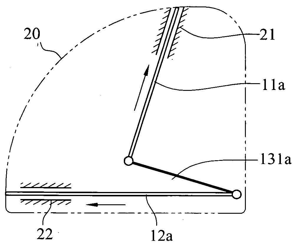
[0011] The paper tray mechanism enclosed in this invention is applicable to machines with movable paper trays, such as printers, scanners, fax machines, all-in-one multifunction centers, and the like. The components contained in the machines mentioned above usually include at least one printing mechanism and at least one paper transporting mechanism. Once the paper is fed into the machine, the paper transporting mechanism will keep transporting it until the printing job is done by the printing mechanism. Since the structures and operation of the aforementioned machines are well known, no further explanation will be provided.

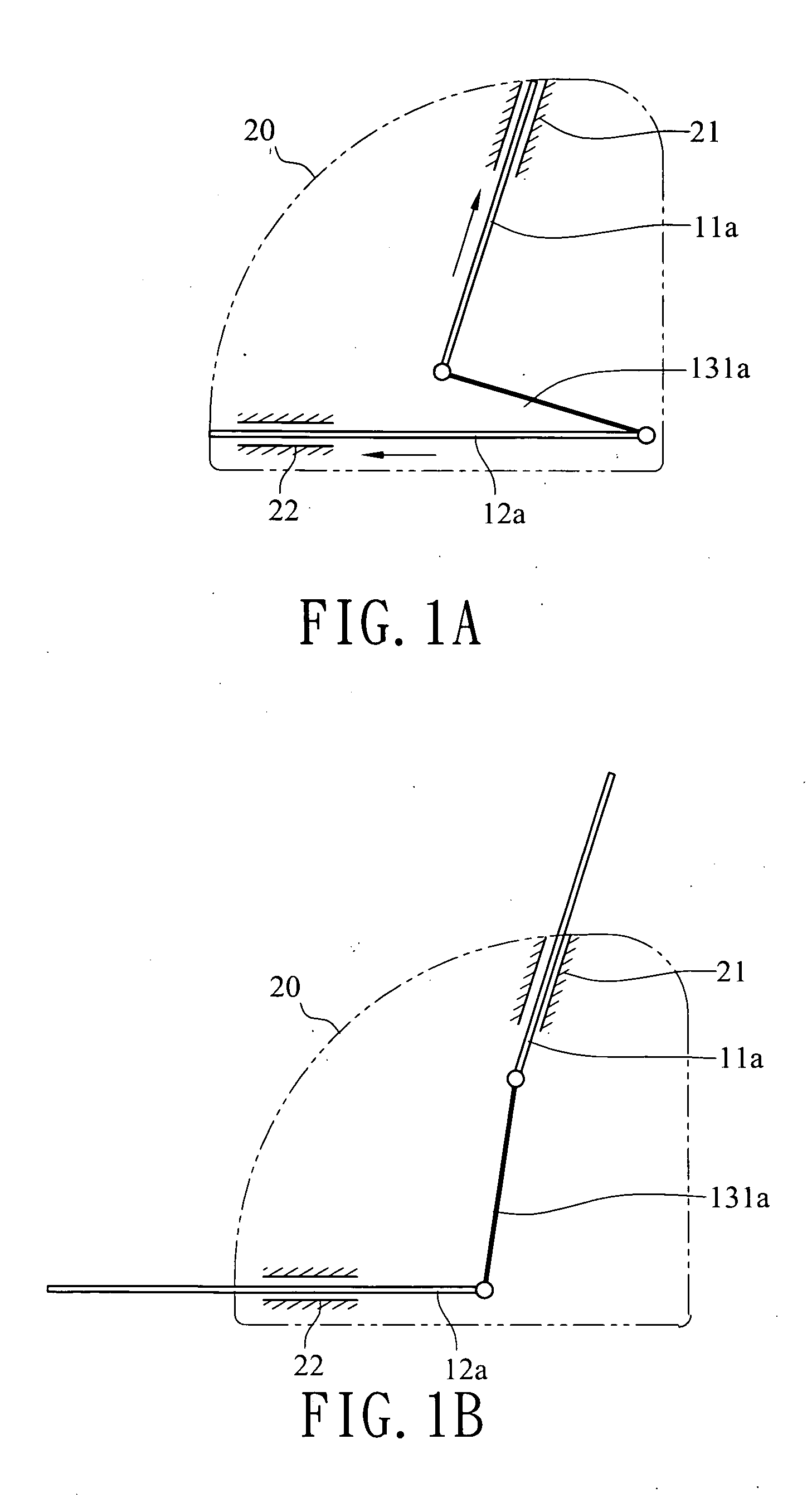
[0012]FIGS. 1A and 1B shows the first embodiment of this invention. According to the first embodiment of this invention, a paper tray mechanism mainly comprises an input paper tray 11a, an output paper tray 12a, and a linkage 131a. FIG. 1A shows the position of the paper trays when they are not in used while in FIG. 1B, both trays are in the ready-to-serve posit...


PUM


Abstract

A paper tray mechanism that is applicable to machines with paper trays, such as printers, scanners, copiers, fax machines, all-in-one multifunction center and the like, comprises an input paper tray, an output paper tray, where both trays are movable and attached to the machine at sides, and an interconnecting mechanism therein between the two trays. When one paper tray is moved by the user, due to the interconnecting mechanism therein between, another paper tray will automatically move simultaneously. Therefore, this invention provides a paper mechanism that only needs one simple and easy step to have both paper trays unfolded / folded and unstashed / stashed so that some spaces are saved for other usage and machine is compact enough to be repacked into the original box.

Description

FIELD OF THE INVENTION [0001] This invention relates to a paper tray mechanism which can be used in machines consisting both input and output paper trays, such as printer, scanner, fax machine, copier, and all-in-1 multifunction center. BACKGROUND OF THE INVENTION [0002] Even though many uses of papers have been replaced by electronic documentations due to concerns of environmental issues, documents still have to be printed on papers under certain circumstances. With the help of machines such as printer, copier, fax machine, scanner, and all-in-one multifunction center, graphics, symbols, texts, and pictures can be printed onto papers for a better visualization and comprehension of the enclosure. A printer, as an instance, usually contains at least one set of the printing mechanism and one set of the paper transporting mechanism. After a paper enters the printer, the paper transporting mechanism passes the paper to the printing mechanism inside the printer to have graphics, symbols,...

Claims


Application Information

Patent Timeline
IPC IPC(8): B41J13/10B65H1/00B65H31/00
CPCB41J13/103B41J13/106B65H1/00B65H31/00B65H2403/53B65H2601/523B65H2405/32B65H2405/35B65H2220/09
Inventor CHENG, CHUNG YI
Owner MULLER CAPITAL
Why Eureka
Try Eureka