Spring energized desktop stapler

a desktop stapler and spring technology, applied in the field of desktop staplers, can solve the problems of jerky experience, difficulty in using a stapler, and difficulty in providing two common loading systems, and achieve the effect of low operating force and convenient us

Inactive Publication Date: 2005-07-19
WORKTOOLS
View PDF31 Cites 116 Cited by
  • Summary
  • Abstract
  • Description
  • Claims
  • Application Information

AI Technical Summary

Benefits of technology

[0021]An advantage of the present invention is that the low operating force makes it easy to use with an extended hand on a desk. It is even practical to press by fingertips.
is that the low operating force makes it easy to use with an extended hand on a desk. It is even practical to press by fingertips.

Problems solved by technology

The result is a jerky experience as the user forces the handle down.
Even though the peak forces are for short durations, they define the difficulty of using a stapler.
In a practical spring actuated stapler these two common loading systems are not easily provided.
It is not possible to slide the track out past the obstruction created by the striker.
Further, since there is an energy storage mechanism linking the striker to the handle in the spring-actuated stapler, it would require a complex design to provide for exposing the staple track by pulling the handle away from the track.
Further, rivet 38 does not provide substantial lateral stiffness to spring 39.

Method used


Image

  • Spring energized desktop stapler
  • Spring energized desktop stapler
  • Spring energized desktop stapler

Examples


Embodiment Construction

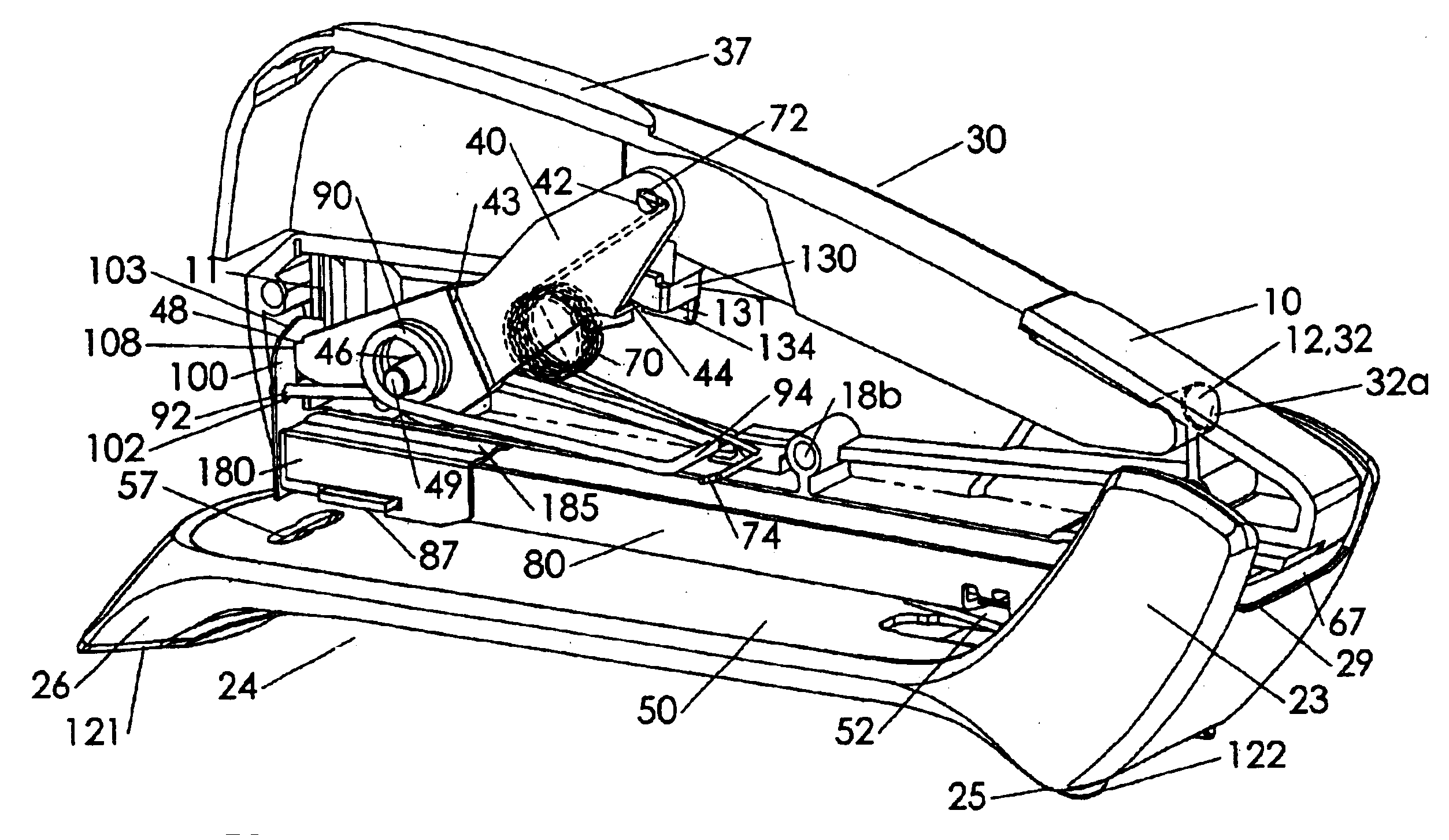
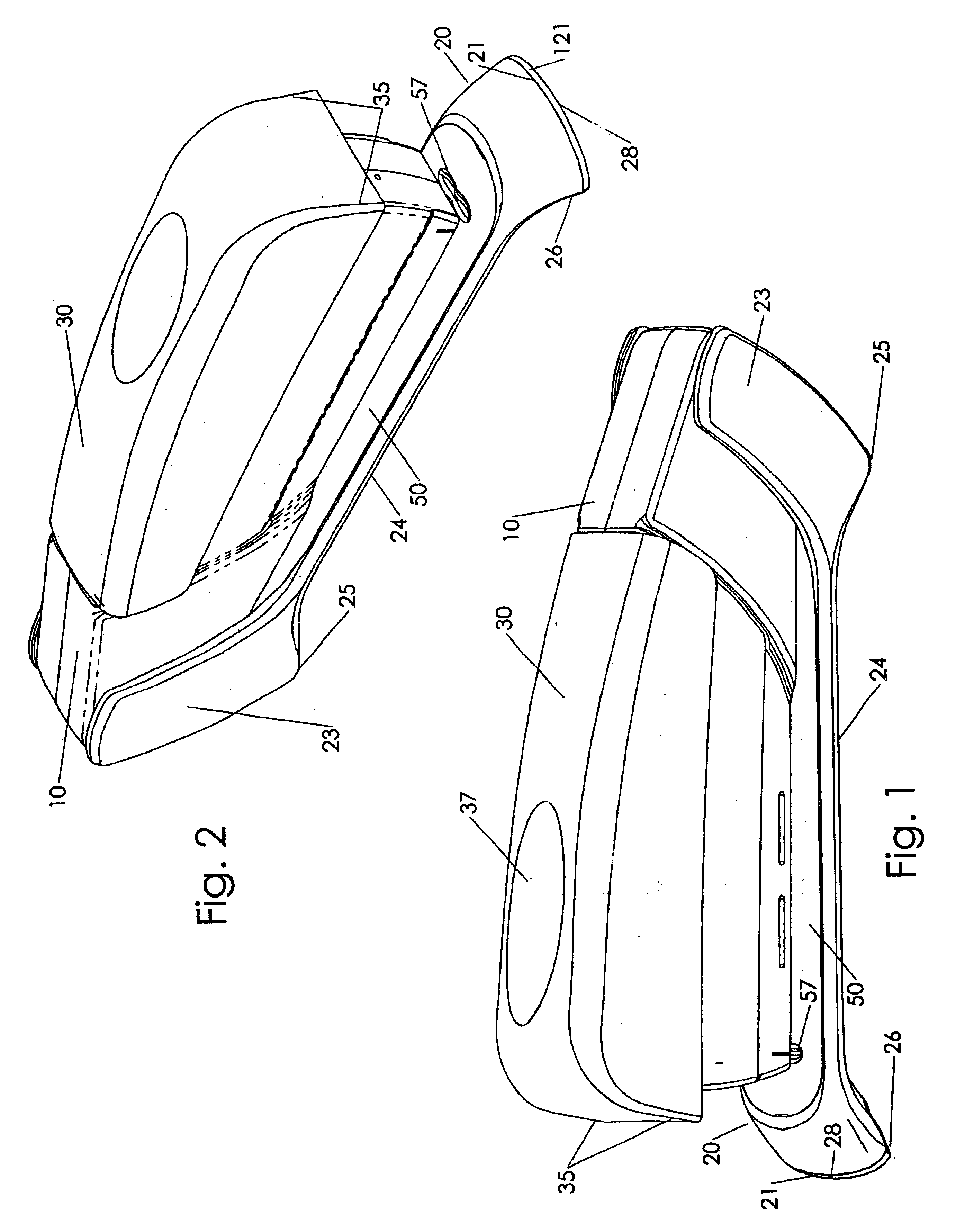
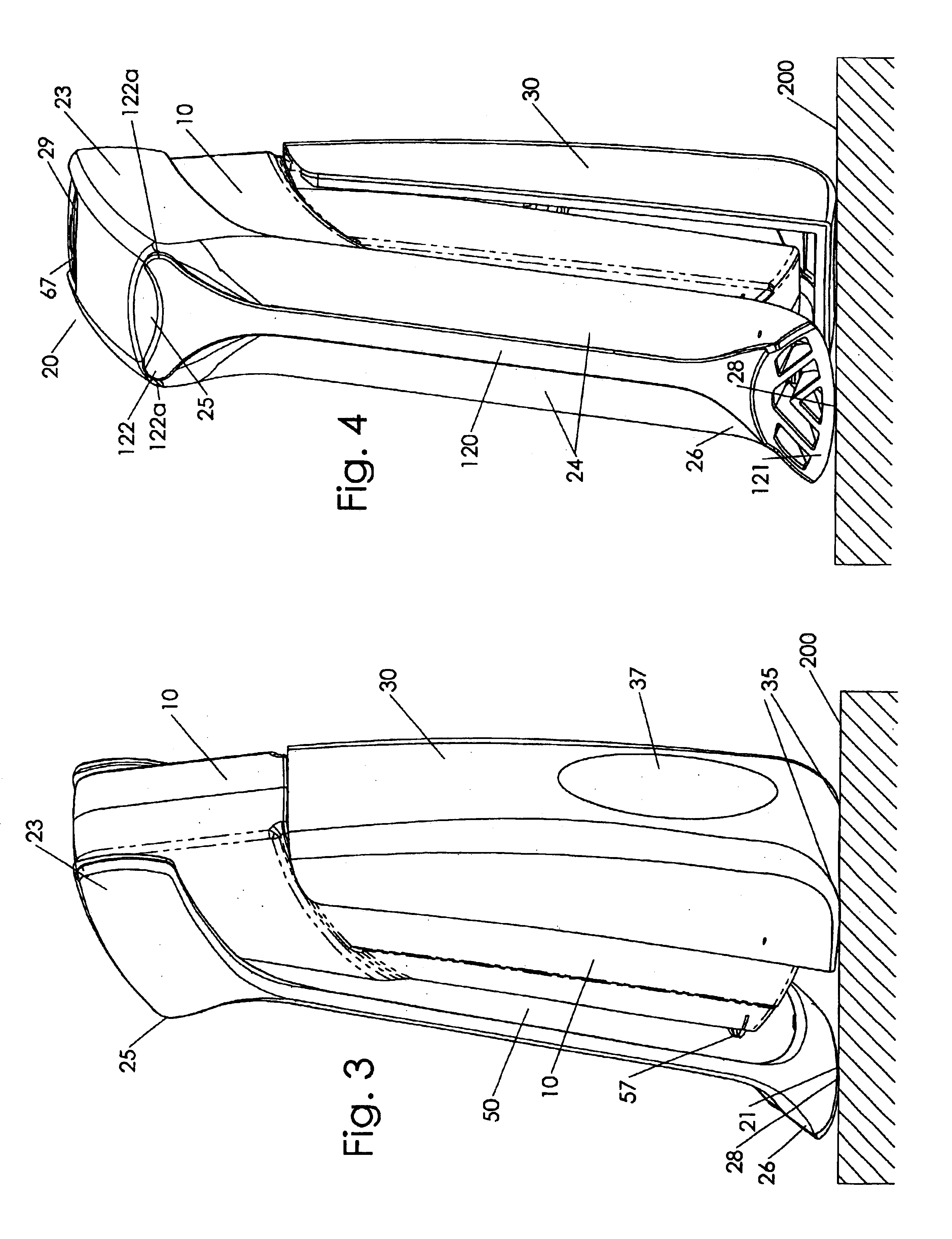
[0058]FIGS. 1 and 2 show a desktop stapler according to the invention in a substantially horizontal orientation, as it would sit upon a desktop. Base 20 can be seen with a raised elongated central under portion or surface 24 and front and rear foot sections 25 and 26. Base 20 may be made from plastic such as glass filled polypropylene, polycarbonate etc. Body 10 includes a left half, FIG. 25, and a right half, FIG. 24. Body 10 may be made from high strength low friction nylon. However other materials may be used such as other plastics or die cast metal. Die cast metal may be desirable if higher weight is needed for design preference. Cover plate 50 encloses cavity 27 of base 20, FIG. 20 to define a central top surface of base 20. Anvil 57 is formed into the material of cover plate 50. Alternately anvil 57 is a separate and possibly movable steel element from cover plate 50. In this case cover plate 50 may be of a plastic or other non-ferrous material. Pivotable handle 30 fits to hou...


PUM


Abstract

A desktop stapler uses a spring to store energy to install staples by impact blow. The force required to fasten papers together is reduced. A very compact mechanism is used, including a dual coil power spring with a nested lever. A multi function base provides a sloped front all the way to down to a desk top surface to guide paper sheets atop the base, easy access for lifting the stapler off a desk, horizontal or vertical resting positions, and integrated soft grip under-surface. The base surrounds the rear of the stapler body to provide a smooth exterior so that the device is natural to use both horizontally and vertically. A simple re-set spring provides a smooth re-set action as the handle is raised. A staple track includes enlargement features to fit a larger staple pusher spring.

Description

FIELD OF THE INVENTION[0001]The present invention relates to desktop staplers. More precisely the present invention discloses improvements to a spring-actuated stapler.BACKGROUND OF THE INVENTION[0002]In a common desktop stapler a striker is linked directly to a handle so that pressing the handle ejects a staple out and through a stack of papers. Three distinct forces must be overcome: breaking off the staple from the rack of staples, piercing the papers, and folding the staple legs behind the papers. As the staple moves through the cycle there are force peaks and force lows. The result is a jerky experience as the user forces the handle down. The handle resists, suddenly gives way, and then resists again. Even though the peak forces are for short durations, they define the difficulty of using a stapler. Empirical information suggest that a conventional stapler requires peak forces of 15 to 30 pounds, depending on the number of paper sheets to be fastened.[0003]It is desirable to li...

Claims


Application Information

Patent Timeline
Patent Type & Authority Patents(United States)
IPC IPC(8): B25C5/00B25C5/02
CPCB25C5/0242B25C5/0292B25C5/10B25C5/1696B25C5/025
Inventor MARKS, JOEL
Owner WORKTOOLS
Why Eureka
Try Eureka