Hinge system used for personal computer and personal computer including the same

a technology of personal computers and hinges, applied in the field of hinges and open-cover type personal computers, to achieve the effect of small force and smooth opening and closing of the firs

Inactive Publication Date: 2005-06-02
KIDA MAKOTO
View PDF9 Cites 19 Cited by
  • Summary
  • Abstract
  • Description
  • Claims
  • Application Information

AI Technical Summary

Benefits of technology

[0010] In view of the above-mentioned problem in the hinge used in the conventional note-type personal computer, it is an object of the present invention to provide a hinge supporting a first portion (for instance, a main body of a note-type personal computer) and a second portion (for instance, an upper cover having a liquid crystal display unit) therewith such that they can open and close relative to each other, which makes it possible to open and close the first and second portions with small force, to smoothly open and close the first and second portions with small force even for children, aged persons or handicapped persons, to keep an upper cover open at an angle (generally, in the range of about 90 to about 145 degrees measured after an upper cover starts opening) at which a user can clearly see a screen of a liquid crystal display unit, and to prevent an upper cover from falling down due to its own weight even at an angle in the range of 150 to 160 degrees (preferably, 150 to 180 degrees or greater). It is also an object of the present invention to provide an open-cover type personal computer including such a hinge.
[0016] It is preferable that each of the first and second parts (16, 50, 17, 70) has two projections (43, 47, 54, 64, 32, 33, 71, 72) arranged circumferentially of a rotation axis of the rotation shaft (21) and spaced away from each other, and one of the two projections of the first part (16, 50) makes contact with one of the two projections of the second part (17, 70), and the other of the two projections of the first part (16, 50) makes contact with the other of the two projections of the second part (17, 70) to provide frictional force for keeping the first and second portions (2, 3) open at the certain angle.
[0026] The projection of the fixed part and the projection of the movable part do not overlap each other axially of the rotation shaft when an angle formed between the first and second portions is between zero (the first and second portions are closed each other) and the above-mentioned range of predetermined angles. Hence, frictional force between the fixed and movable parts is relatively small, and thus, a user can open and close the first and second portions each other with small force. Thus, even children, aged persons and handicapped persons can smoothly open and close the first and second portions each other with small force.
[0027] In addition, by appropriately setting the range of predetermined angles, it is possible to keep an upper cover having a liquid crystal display unit therein open at an angle (generally, in the range of about 90 to about 145 degrees measured after an upper cover starts opening) at which a user can readily see a screen of the liquid crystal display unit, for instance, in a note-type personal computer. Furthermore, it is possible to prevent an upper cover from falling down due to its own weight even at an angle in the range of 150 to 160 degrees (preferably, 150 to 180 degrees or greater) measured after the upper cover starts opening.
[0028] In accordance with Japanese Patent Application Publication No. 2004-3594, since the resistive hinge has a resistive force which is constant independently of an angle formed between an upper cover and a main body, if the resistive force to be generated when an upper cover starts opening is reduced, the upper cover would fall down due to its own weight at 150 to 160 degrees. In contrast, the hinge in accordance with the present invention can reduce a resistive force thereof when an upper cover starts opening, and can increase a resistive force thereof only in the range of angles at which a user wants to stop the upper cover, and thus, a user is surely able to stop the upper cover at his / her desired angle. It is possible to prevent an upper cover from falling down due to its own weight even at an angle in the range of 150 to 160 degrees (preferably, 150 to 180 degrees or greater) measured after the upper cover starts opening.

Problems solved by technology

However, the conventional note-type personal computer 100 is accompanied with a problem that since gravitational force of the upper cover 101 of about 5.8 kgf / cm at maximum is added to the resistance of resistive hinge 104 of 6 kgf / cm, a force for stopping rotation of the upper cover 101 is reduced when the upper cover 101 is open at 150 degrees or greater, and resultingly, the upper cover 101 falls down due to its own weight, and that if the resistive hinge 104 is designed to have a greater resistance, the upper cover 101 would not fall down due to its own weight, but it would be necessary to apply a greater force to the upper cover 101 for opening the same.

Method used


Image

  • Hinge system used for personal computer and personal computer including the same
  • Hinge system used for personal computer and personal computer including the same
  • Hinge system used for personal computer and personal computer including the same

Examples


first embodiment

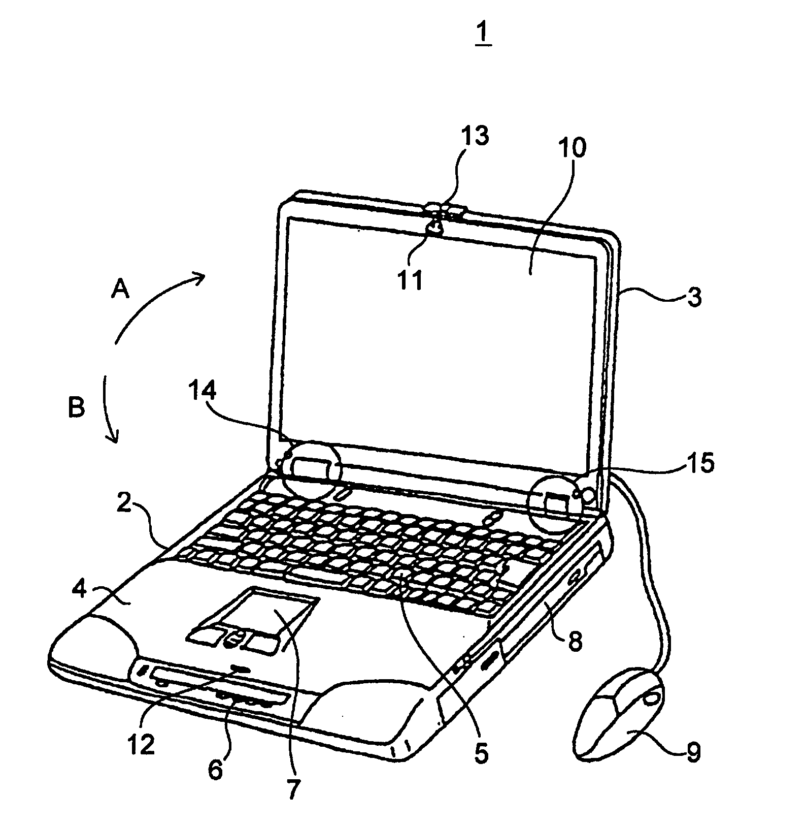
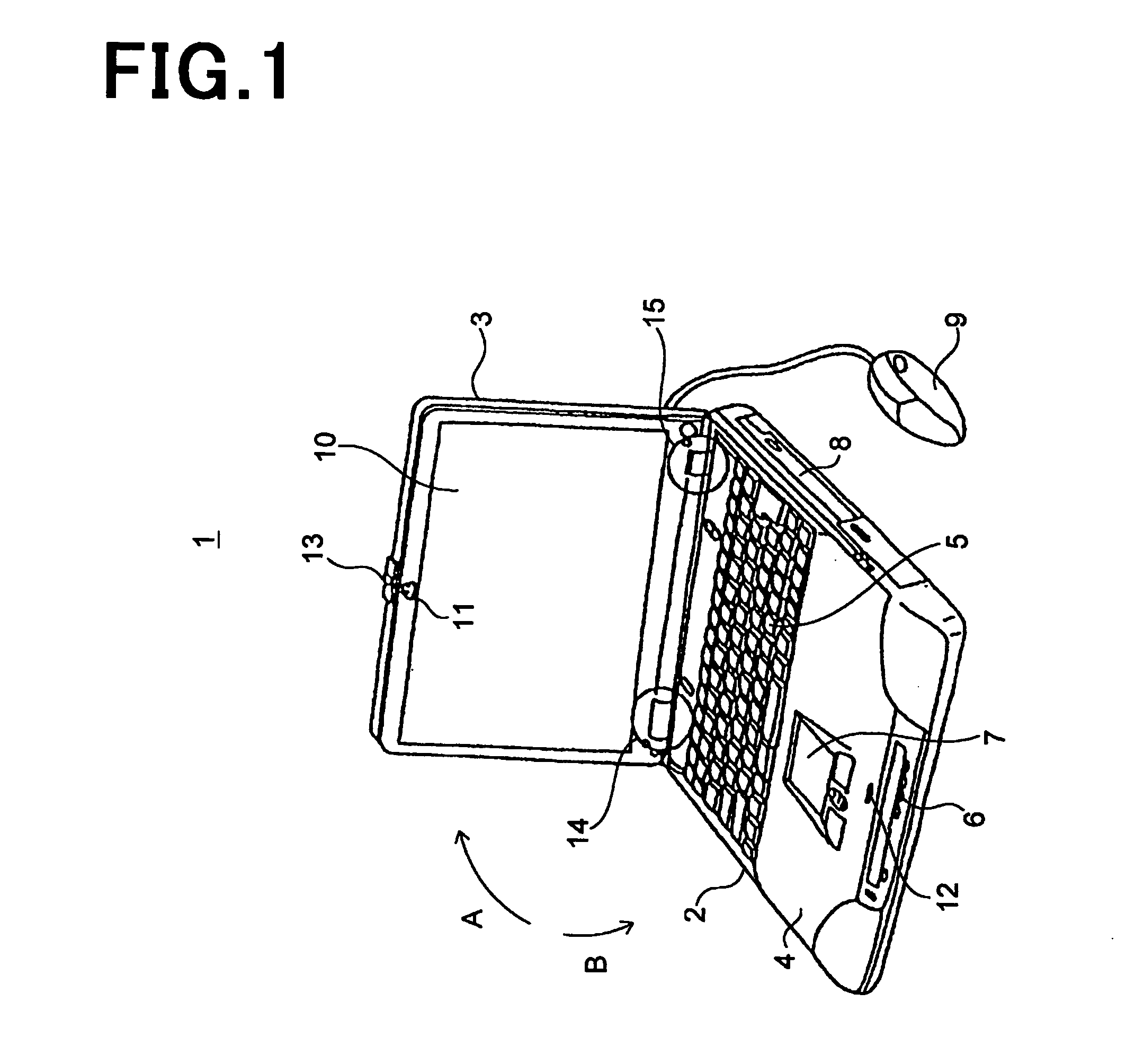
[0042]FIG. 1 is a perspective view illustrating a note-type (open-cover type) personal computer 1 in accordance with the first embodiment.

[0043] As illustrated in FIG. 1, the note-type personal computer 1 is comprised of a thin box-shaped main body (first portion) 2, and an upper cover (second portion) 3 supported at an upper edge at the rear of the main body 2 such that the upper cover 3 can open and close relative to the main body 2. As mentioned later, the upper cover 3 is designed to be able to be kept open relative to the main body 2 at a certain angle in the range of predetermined angles.

[0044] The main body 2 has an upper surface 4 located inwardly when the upper cover 3 is closed to the main body 2. On the upper surface 4 are arranged a keyboard 5, various operation buttons 6, and a track pad 7. On a side of the main body 2 are arranged a CD-ROM drive 8, a FD drive (not illustrated), and various terminals (not illustrated).

[0045] A mouse 9 is connected to the main body 2 ...

second embodiment

[0122] In the above-mentioned first embodiment, the force for stopping the rotation of the upper cover 3 can be generated only when the upper cover 3 opens relative to the main body 2 at an angle equal to or smaller than about 165 degrees, because of the structures of the fixed washer 16 and the movable washer 17. It is impossible to generate the force when the upper cover 3 opens relative to the main body 2 at an angle equal to or greater than 180 degrees, even though the downwardly-inclining portions 44 and 48 had a minimum width.

[0123] Hence, the second embodiment is designed to include a fixed washer 50 (FIG. 5) and a movable washer 70 (FIG. 6) both of which are capable of providing a broader range of angles at which the above-mentioned force can be generated, in place of the fixed washer 16 and the movable washer 17 mentioned in the first embodiment.

[0124] Since the second embodiment is identical in structure with the first embodiment except that the fixed washer 50 and the m...


PUM


Abstract

A hinge supporting first and second portions such that they are open and closed relative to each other, including a rotation shaft fixed to the second portion and supported by the first portion so as to be rotatable around a rotation axis thereof relative to the first portion, first and second parts into which the rotation shaft is inserted, and an energizer for pushing the movable part towards the fixed part. The first part is fixed to the first portion so as to be rotatable around the rotation axis relative to the first part. The second part is axially movable relative to the rotation shaft and not rotatable around a rotation axis thereof, and rotates together with the rotation shaft. Each of the first and second parts has a projection projecting towards each other. The projections overlap each other axially of the rotation shaft when the first and second portions are open each other at a certain angle in the range of predetermined angles.

Description

BACKGROUND OF THE INVENTION [0001] 1. Field of the Invention [0002] The present invention relates a hinge and an open-cover type personal computer including the same. [0003] 2. Description of the Related Art [0004] A note-type personal computer is usually designed to have a mechanism which makes it possible to lift an upper cover up from a main body with small force, and keep the upper cover open at a certain angle relative to the main body. [0005]FIG. 7 is a perspective view illustrating a conventional note-type personal computer 100 suggested in Japanese Patent Application Publication No. 2004-3594.[0006] As illustrated in FIG. 7, an upper cover 101 into which a liquid crystal display unit is incorporated is supported at opposite ends thereof relative to a main body 102 such that the upper cover 101 can open and close relative to the main body 102. [0007] One of supporters 103 is comprised of a resistive hinge 104 so as to produce a force for stopping rotation of the upper cover 1...

Claims


Application Information

Patent Timeline
Patent Type & Authority Applications(United States)
IPC IPC(8): H05K5/02E05D11/10E05F1/12G06F1/16H05K5/03
CPCE05D11/1078E05F1/1215E05Y2900/606G06F1/1616Y10T16/540255Y10T16/54038Y10T16/540345Y10T16/52Y10T16/5387G06F1/1681G06F1/1613
Inventor KIDA, MAKOTO
Owner KIDA MAKOTO
Why Eureka
Try Eureka