
Construction machine

a construction machine and construction technology, applied in mechanical machines/dredgers, roofs, doors, etc., can solve the problems of deterioration of the operating environment, rattling or vibrating, and limited range which would not be effective for minimizing

Active Publication Date: 2007-06-14
NIHON KENKI CO LTD
View PDF5 Cites 19 Cited by
  • Summary
  • Abstract
  • Description
  • Claims
  • Application Information

AI Technical Summary

Benefits of technology

[0015] In view of the above-discussed problems with the prior art, it is an object of the present invention to provide a construction machine which is arranged to minimize a sideward outrunning of an opened cab door beyond the width of a vehicular body of the machine, permitting to operate the machine smoothly with the cab door in opened state and securing a broader space within the cab to provide an improved working environment.
[0016] It is another object of the present invention to provide a construction machine which permits to open and close a cab door smoothly to ensure improved working efficiency, for example, even under snowing weather conditions.

Problems solved by technology

However, considering positional relations with the cab and other structures, the relocation of the cab is feasible only in a limited range which would not be effective for minimizing a sideward outrunning of an opened cab door to a sufficient degree.
In such a case, it becomes difficult to secure a sufficient space within the cab, resulting in deteriorations in operating environment.
The first door panel is not fixed to the side of the cab box, so that it is put in rattling or vibratory movements and considerably deteriorated in durability, due to plays in hinges which rotatably support the first door panel.
Therefore, when the machine is used at a working site in a cold district or in winter, snow falls on the projected part of the revolving frame while the machine is operated or parked on a snowing site, to make it difficult to open the door, as a result degrading efficiency of operation.
Besides, at the time of a ground excavating operation, soil tend to deposit and accumulate on the projected part of the revolving frame.

Method used


Image

  • Construction machine
  • Construction machine
  • Construction machine

Examples


Embodiment Construction

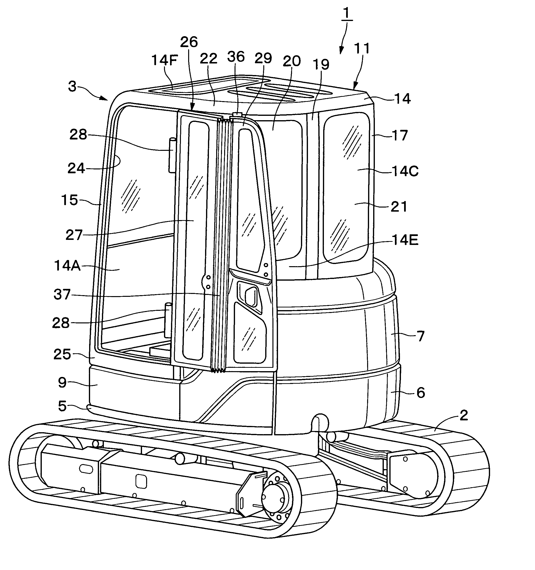
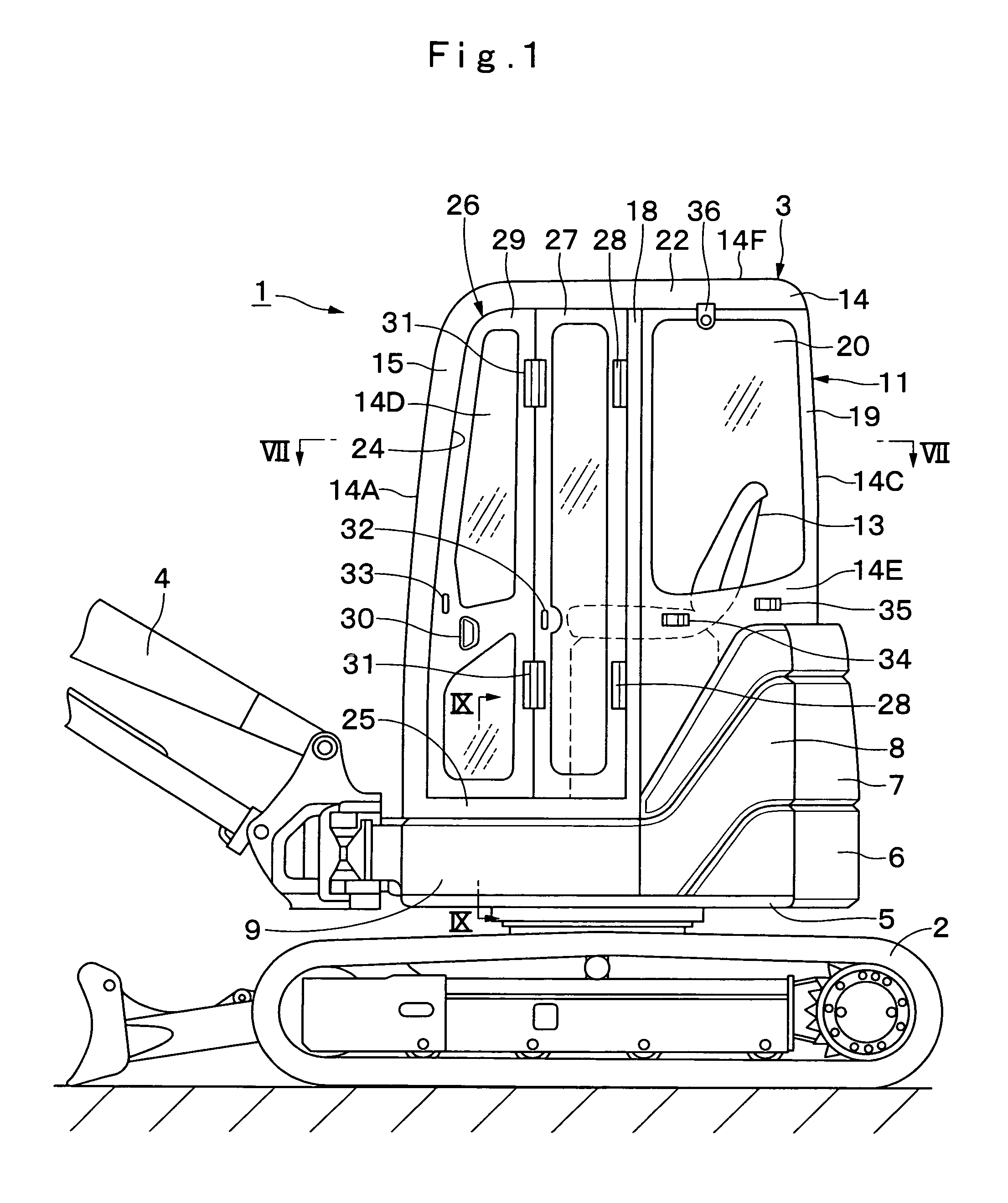
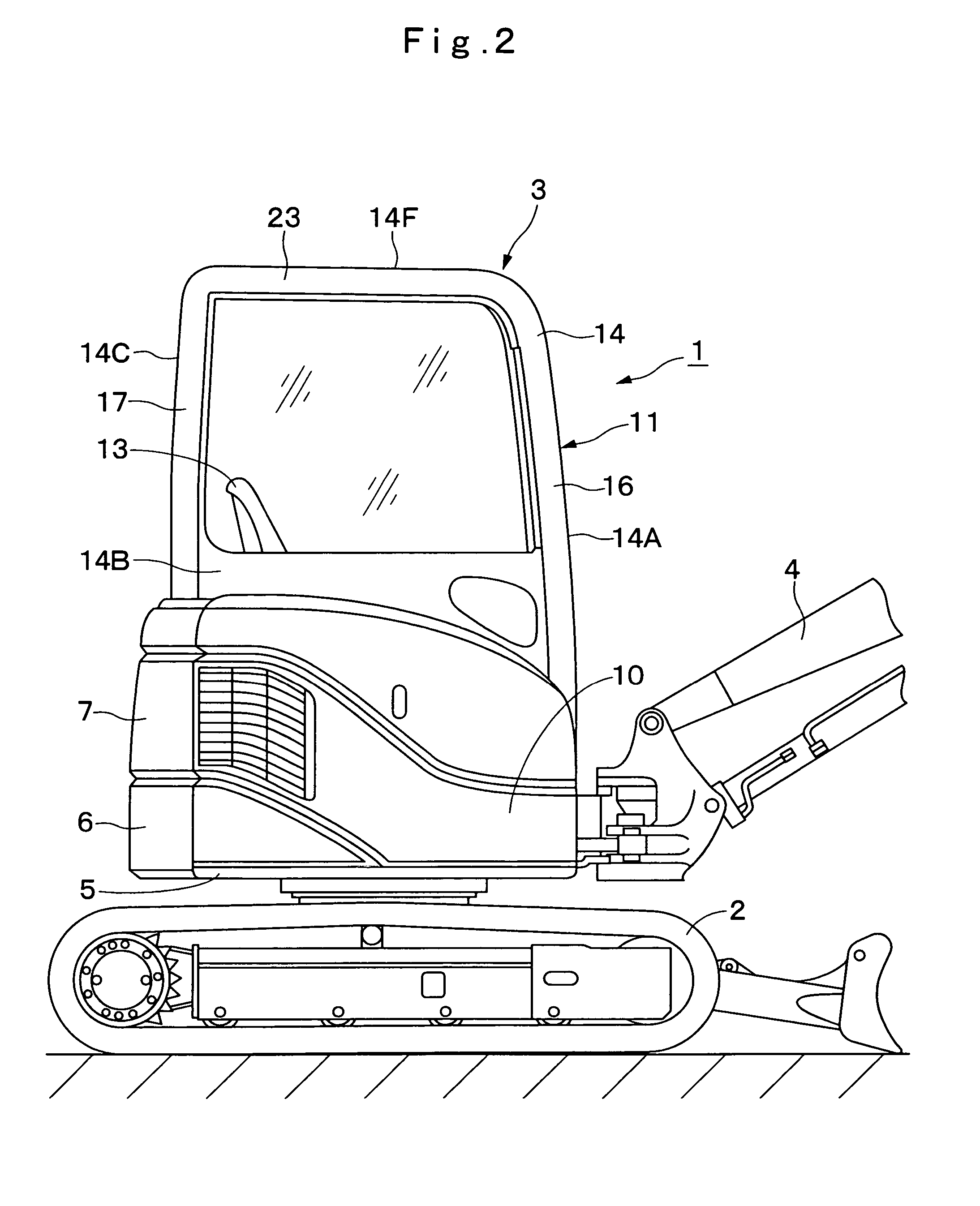
[0048] Hereafter, with reference to FIGS. 1 through 13, the present invention is described more particularly by way of its preferred embodiments which are applied to a hydraulic excavator by way of example.

[0049] In the drawings, indicated at 1 is a hydraulic excavator, which is largely constituted by an automotive vehicular lower structure 2, an upper revolving structure 3 which is rotatably mounted on the vehicular lower structure 2, and a working mechanism 4 which is liftably mounted on the front side of the upper revolving structure and to be put in a ground excavating operation or the like. In this instance, the hydraulic excavator is constructed as a small turn type, more particularly, as a small back swing type having the upper revolving structure 3 formed substantially in a circular shape.

[0050] Further, as shown in FIGS. 1 to 5, the upper revolving structure 3 includes a revolving frame 5 which is formed as a support structure by a combination of bottom and vertical plate...


PUM


Abstract

A folding type door is fitted in a cab box. Two door panels and are disposed substantially in the same vertical plane as a left side cover of an upper revolving structure when said door in a closed position. Catches and are provided in a left rear side section of the cab box. Provided on door panels and of the folding type door are strikers and to be attachably or detachably engaged with the catches and separately of each other. When the folding type door is opened, the respective door panels and are each retained in an open door position by engagement of two sets of strikers and and catches and which prevents rattling movements of each door panel to retain the folding type door in a stabilized state.

Description

TECHNICAL FIELD [0001] This invention relates to a construction machine which can be used, for example, as a hydraulic excavator and which is furnished with a cab to be occupied by an operator at the control of the machine. BACKGROUND ART [0002] Generally, it has been known to provide a cab on a construction machine like a hydraulic excavator. A cab on a construction machine of this sort is often fitted with a door to be opened and closed by an operator (e.g., as disclosed in Patent Literatures 1, 2 and 3 below). [0003] Patent Literature 1: Japanese Patent Laid-Open No. H1-198929 [0004] Patent Literature 2: WO99 / 61711 [0005] Patent Literature 3: Japanese Patent Laid-Open No. H11-100864 [0006] Prior art hydraulic excavators of this sort are largely constituted by a vehicular lower structure and an upper revolving structure which is rotatably mounted on the vehicular lower structure, and a cab is usually built on a revolving frame of the upper revolving structure. Normally, the cab is...

Claims


Application Information

Patent Timeline
IPC IPC(8): B62D33/06B60J5/00E02F3/34E02F9/16
CPCB60J5/0487E02F3/325E02F9/163E02F9/16
Inventor ISHII, HAJIMEKIMURA, SHOGOTANAKA, TOMOYUKI
Owner NIHON KENKI CO LTD
Learn More