Windproof umbrella

Inactive Publication Date: 2011-05-12
YOU CHING CHUAN
View PDF12 Cites 17 Cited by
  • Summary
  • Abstract
  • Description
  • Claims
  • Application Information

AI Technical Summary

Benefits of technology

[0009]It is therefore one object of the invention to provide a improved windproof umbrella comprising a shank; a runner on the shank; a plurality of ribs; a canopy; a plurality of stretchers; a plurality of U-shaped first joints each secured onto the rib; a plurality of U-shaped second joints each slidably put on the rib; a plurality of U-shaped third joints each secured onto the stretcher; a plurality of auxiliary rods; and a plurality of sets of first, second, and third pivotal members. The first pivotal member is formed at the other end of the stretcher

Problems solved by technology

Typical symmetrical umbrellas are not capable of withstanding strong wind which exerts a force against the inner surface of canopy.
For typical non-symmetrical umbrellas, they even

Method used


Image

  • Windproof umbrella
  • Windproof umbrella
  • Windproof umbrella

Examples


Embodiment Construction

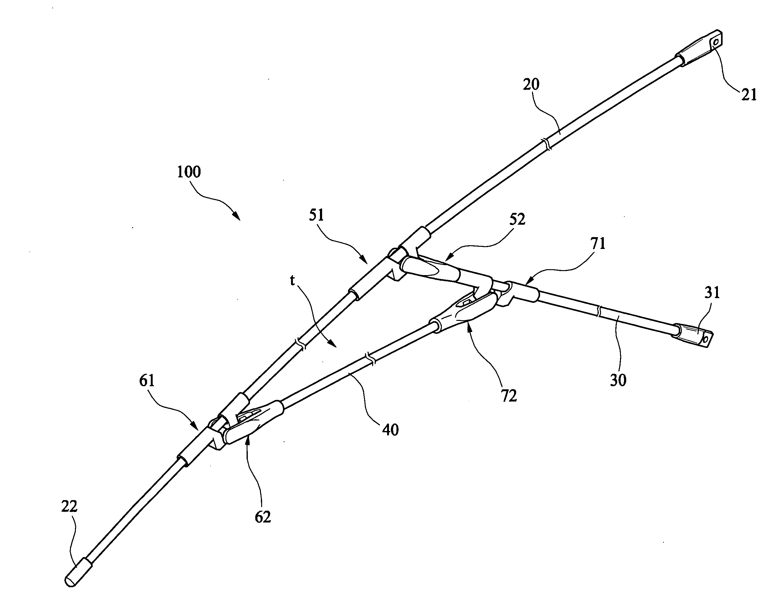
[0034]Referring to FIGS. 5 to 8, a windproof umbrella in accordance with a first preferred embodiment of the invention comprises the following components as discussed in detail below.

[0035]Frame 100 of the windproof umbrella comprises a central shank 10, a plurality of ribs 20, a plurality of stretchers 30, and a plurality of auxiliary rods 40. A canopy 101 is covered over the frame 100 (see FIG. 8).

[0036]The shank 10 comprises an upper hub 11 with the ribs 20 radially extending therefrom, and a spring biased runner 12 under the hub 11 with the stretchers 30 radially extending therefrom.

[0037]The rib 20 comprises, between its releasable first cup 21 at one end and a releasable second cup 21 at the other end, a first joint 51 proximate to the first cup 21 and a second joint 61 proximate to the second cup 22. The first cup 21 is pivotably connected to the hub 11. The first joint 51 comprises a U-shaped member 511, a first hollow member 512 extending from one end of the U-shaped member...


PUM


Abstract

A windproof umbrella includes a shank (10); a runner (12) on the shank (10); ribs (20); a canopy (101); stretchers (30); U-shaped first joints (51) each secured onto the rib (20); U-shaped second joints (61) each slidably put on the rib (20); U-shaped third joints (71) each secured onto the stretcher (30); auxiliary rods (40); and sets of first, second, and third pivotal members (52, 62, and 72). The first pivotal member (52) is formed at the other end of the stretcher (30) and is pivotably connected to the first joint (51). The second pivotal member (62) is formed at one end of the auxiliary rod (40) and is pivotably connected to the second joint (61). The third pivotal member (72) is formed at the other end of the auxiliary rod (40) and is pivotably connected to the third joint (71). In response to strong wind, the second joint (61) slides to change an angle between the rib (20) and the stretcher at the first joint (51). Therefore, the wind escape capability of windproof umbrella (1) of the invention is greatly increased.

Description

BACKGROUND OF THE INVENTION[0001]1. Field of Invention[0002]The invention relates to umbrellas and more particularly to a windproof umbrella with improved characteristics.[0003]2. Description of Related Art[0004]Conventionally, umbrellas are classified as symmetrical ones having a circular canopy with a shank extending downward from a center of the canopy and non-symmetrical ones having a non-circular canopy with a shank extending downward from a non-central position of the canopy as shown in FIG. 1. As shown in FIG. 2, canopy area to the left of the shank has a length S and canopy area to the right of the shank has a length L greater than length S.[0005]Typical symmetrical umbrellas are not capable of withstanding strong wind which exerts a force against the inner surface of canopy. Thus, it is often that the canopy inverts from its normal operable position to an outwardly convex or bowed position. For typical non-symmetrical umbrellas, they even provide little resistance to invers...

Claims


Application Information

Patent Timeline
IPC IPC(8): A45B25/06A45B11/00
CPCA45B25/22A45B25/10
Inventor YOU, CHING-CHUAN
Owner YOU CHING CHUAN
Why Eureka
Try Eureka