Pressure sensor, method of producing the sensor, and in-cylinder pressure detection structure of internal combustion engine

Inactive Publication Date: 2005-09-29
BOSCH AUTOMOTIVE SYST CORP
View PDF4 Cites 28 Cited by
  • Summary
  • Abstract
  • Description
  • Claims
  • Application Information

AI Technical Summary

Benefits of technology

[0021] In the structure for detecting a cylinder internal pressure of an internal combustion engine according to this invention, an auxiliary part which is normally mounted on an internal combustion engine is used to dispose the pressure sensor within the combustion chamber of the internal combustion engine, thus dispensing with a mounting space on the cylinder head while facilitating a mounting and a replacement with a very slight cost-up. A combustion pressure or a manner of a fuel injection can be preci

Problems solved by technology

Accordingly, when the pressure sensor is installed within a combustion chamber of an internal combustion engine, for example, signal transmitting means such as the electrode and an output lead wire, not shown, are directly exposed to a high temperature environment within the combustion chamber, causing a problem of the durability.
In addition, if a carbon is deposited during use over a prolonged period of time, there is a likelihood that a conduction may occur between the both electrodes.
In particular, there remains a problem that it is difficult to catch the timing of initiation of the ignition exactly.
However, it is subject to friction heating between the sheath and the housing, and it cannot be evaluated as exhibiting an excellent accuracy of detection.
In addition, there is a tendency that the interior of the housing assumes a high pressure, presenting a likelihood of presenting a problem in respect of the durability as a result of a failure of a hermetic seal of the sheath and the breakage of the heater.
In the pressure sensor

Method used


Image

  • Pressure sensor, method of producing the sensor, and in-cylinder pressure detection structure of internal combustion engine
  • Pressure sensor, method of producing the sensor, and in-cylinder pressure detection structure of internal combustion engine
  • Pressure sensor, method of producing the sensor, and in-cylinder pressure detection structure of internal combustion engine

Examples


Embodiment Construction

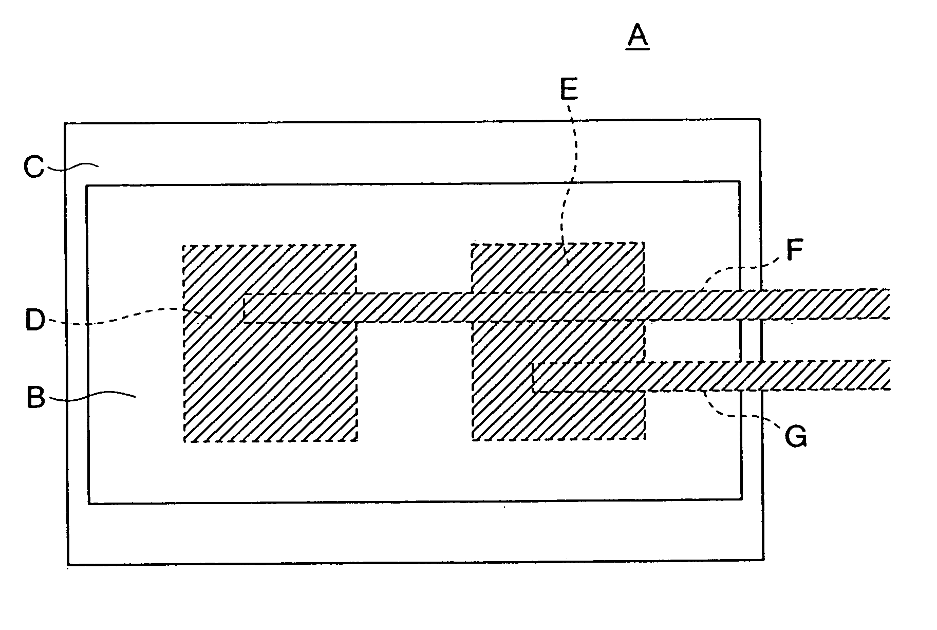
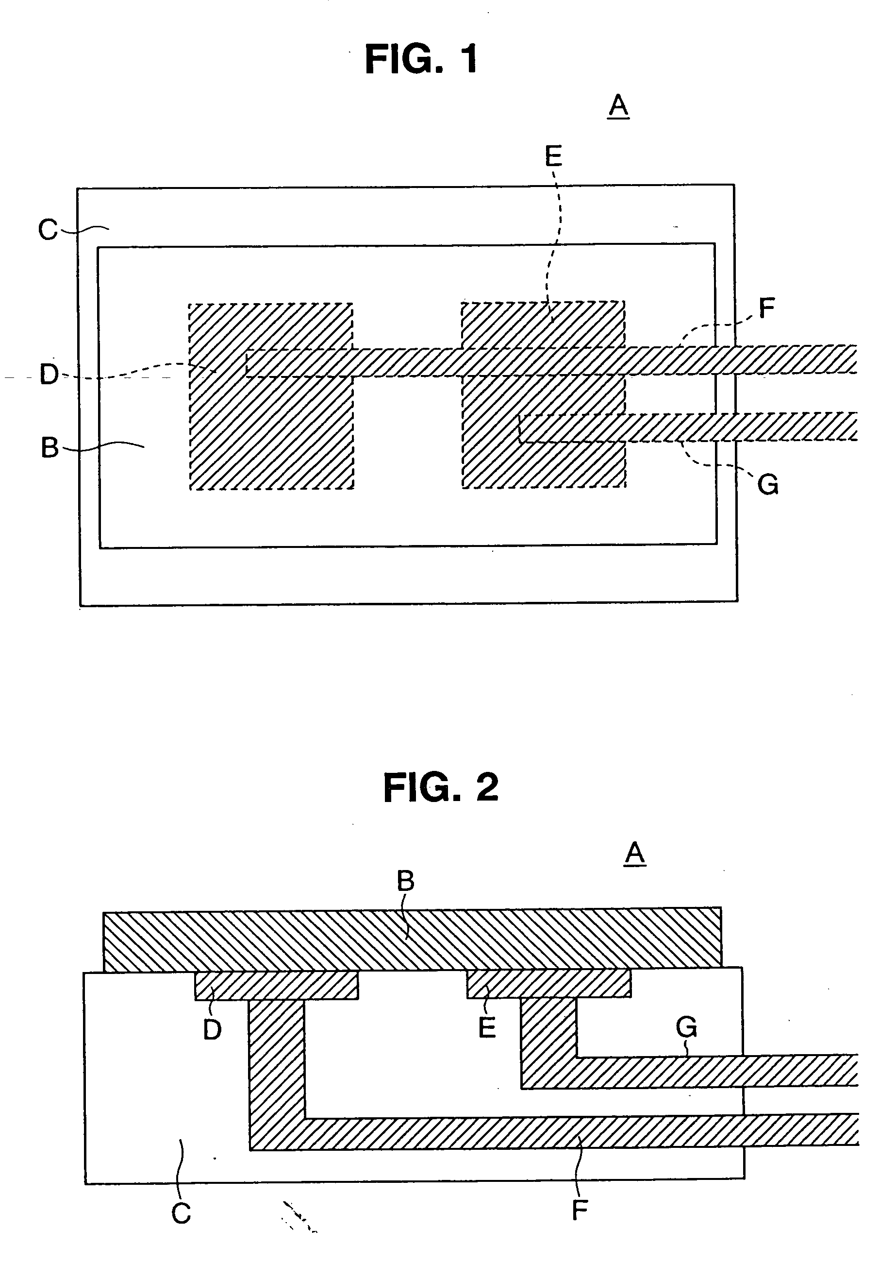
[0065] Several embodiments of the present invention shown in the drawings will now be described. A pressure sensor A includes a piezoelectric element B in the form of a thin film, which is mounted on a base material C formed of an insulating material such as insulating ceramics. In the embodiment, the piezoelectric element B uses a thin film of aluminium nitride (AlN) having a C-axis orientation.

[0066] Signal transmitting means which delivers an electrical signal detected by the thin film of the piezoelectric element B comprises a first and a second output electrode D and E, which are disposed on the surface of the piezoelectric element B which is disposed toward the base material C. Output lead wires F and G which also define the signal transmitting means and which are connected to the electrodes D and E, respectively, pass through the inside of the base material C. Thus, in distinction to the prior art arrangement (Japanese Laid-Open Patent Application No. 10-122,984), the pair o...


PUM

PropertyMeasurementUnit
Pressureaaaaaaaaaa
Internal pressureaaaaaaaaaa

Abstract

In a pressure sensor A according to the presenting invention, a piezoelectric element B formed by a thin film of aluminium nitride is mounted on a base material C of an insulating material, and output electrodes D and E and output lead wires F and G which transmit a signal detected by the piezoelectric element B are mounted on the side of the base material C. The pressure sensor A is directly mounted on a cylinder head e of an internal combustion engine, or is mounted on the outer surface of a heater L which is secured at the free end of a glow plug K, whereby it is disposed to face a combustion chamber h. A combustion pressure or oscillations during the operation of the engine can be detected with a high sensitivity.

Description

TECHNICAL FIELD [0001] The present invention relates to a pressure sensor, for example, a pressure sensor installed within a cylinder of an internal combustion engine for detecting a combustion pressure and oscillations within the cylinder during operation of the engine. The invention also relates to a method of manufacturing such a pressure sensor and to a structure utilizing the pressure sensor for detecting cylinder internal pressure of the internal combustion engine. BACKGROUND ART [0002] A variety of power train control techniques are used in an internal combustion engine with an intent to cope with the purification of exhaust gases and a compatible attainment of improvements in the fuel cost and the engine performance. If it were possible to detect a change in the combustion pressure within the cylinder exactly and to detect a manner of injection from an injector exactly, an optimum control of ignition timing, a more precise control of fuel injection and a rapid accommodation ...

Claims


Application Information

Patent Timeline
IPC IPC(8): G01L23/10G01L23/22
CPCF02P19/028F23Q7/001F23Q2007/004Y10T29/49004G01L23/222F23Q2007/002G01L23/10F02M57/005F02M2200/247
Inventor TOMITA, NAOHIROKASUKAWA, KAZUHISA
Owner BOSCH AUTOMOTIVE SYST CORP
Why Eureka
Try Eureka