
Mixed driving type vehicle running controller and vehicle thereof

An operation control, hybrid drive technology, applied in hybrid vehicles, control devices, power devices, etc., can solve problems such as high fuel costs, loud internal combustion engine noise, and inability to maintain remaining capacity in batteries

Inactive Publication Date: 2003-07-09
YAMAHA MOTOR CO LTD
View PDF2 Cites 20 Cited by
  • Summary
  • Abstract
  • Description
  • Claims
  • Application Information

AI Technical Summary

Problems solved by technology

[0013] As an electric vehicle with both the above-mentioned electric motor and internal combustion engine, depending on the speed difference between the target vehicle speed and the detected vehicle speed, the rear wheels are driven by both the electric motor and the internal combustion engine or only by the electric motor. The battery for the power supply of the motor maintains an appropriate remaining capacity, or the noise of the internal combustion engine is large, and the fuel cost is high, etc.

Method used


Image

  • Mixed driving type vehicle running controller and vehicle thereof
  • Mixed driving type vehicle running controller and vehicle thereof
  • Mixed driving type vehicle running controller and vehicle thereof

Examples


Embodiment Construction

[0091] Hereinafter, embodiments of the present invention will be described with reference to the accompanying drawings.

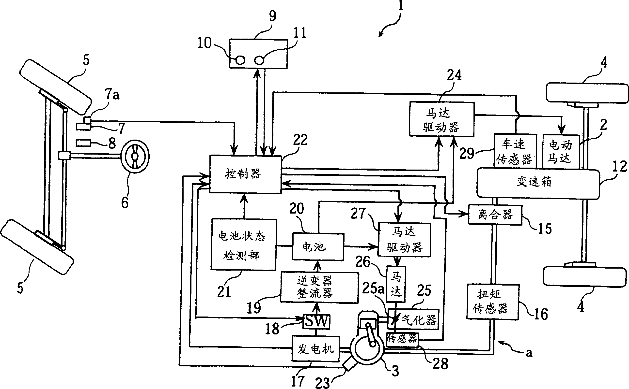
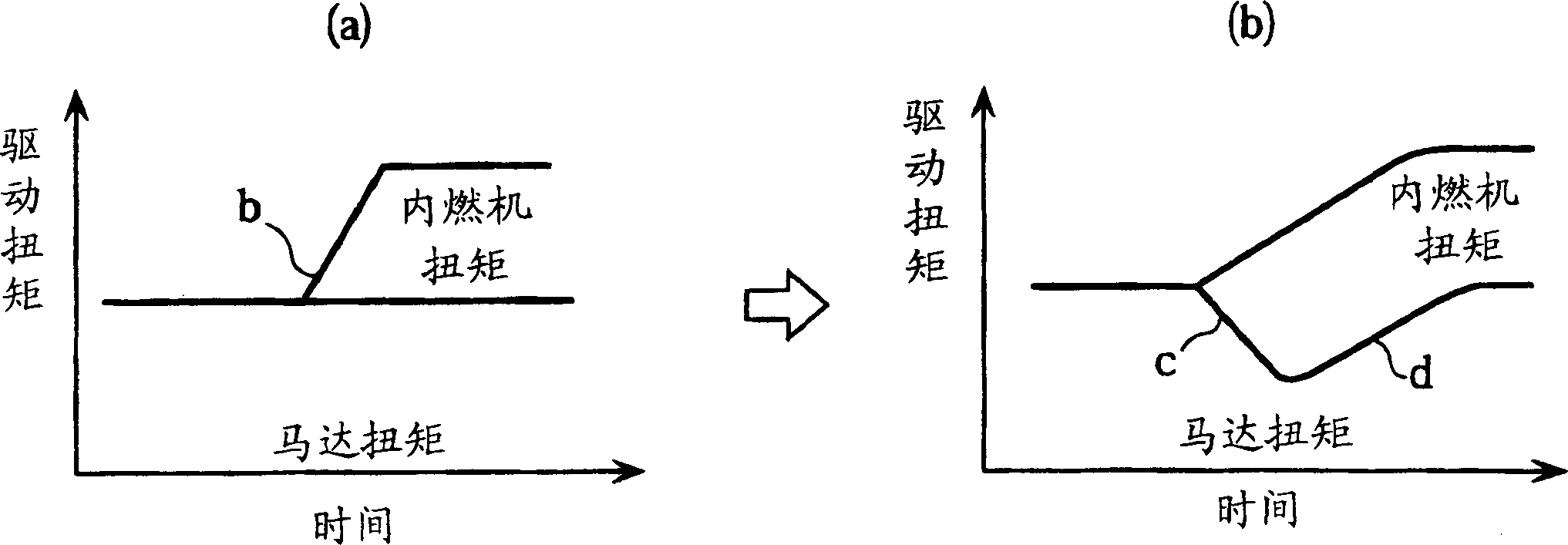
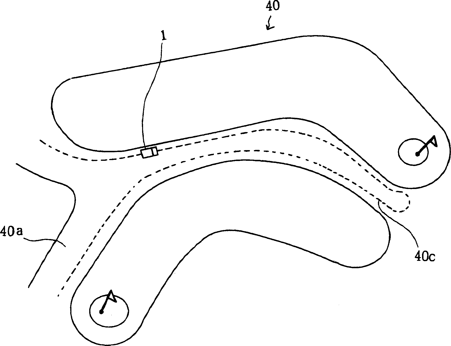
[0092] Figure 1 to Figure 4 It is a drawing for explaining the operation control device for a hybrid vehicle, specifically a golf cart, provided by a first embodiment of claims 1 and 3 of the present invention, figure 1 is its structure diagram, figure 2 is the driving torque characteristic graph to explain the operation, image 3 , Figure 4 It is a schematic diagram showing the usage status of a golf cart.

[0093] figure 1 Among them, number 1 represents a golf cart, and this golf cart 1 has an electric motor 2 and an internal combustion engine 3 as a drive source for driving a pair of left and right rear wheels (drive wheels) 4, 4, and controls the left and right wheels with a steering wheel 6. A pair of front-wheels 5,5 turns and walks.

[0094] The structure of said golf cart 1 is to be able to select any of the following walking modes, the ma...


PUM


Abstract

The invention provides a drive control device for a hybrid vehicle capable of reducing the discomfort of an occupant by releasing a shock in applying the driving force of an internal combustion engine. In the drive control device for a hybrid vehicle including an electric motor (2) and an internal combustion engine (3), when a load is less than a predetermined reference value, the drive wheels are driven only by driving force of the electric motor (2); when the load is the reference value or more, the drive wheels are driven by driving force of both the electric motor (2) and the internal combustion engine (3). A drive force detecting sensor (16) for detecting the drive force is arranged in midway of a drive force transmission system from the internal combustion engine (3) to the drive wheel (4). During the drive wheels are driven by driving force of both the electric motor (2) and the internal combustion engine (3), the controller preferably controls the electric motor to reduce the drive force provided by the electric motor when the drive force detected by the drive force detecting sensor (16) changes to a rising direction based on a rate of change over a predetermined reference value.

Description

technical field [0001] The present invention relates to an operation control device for a hybrid vehicle in which drive wheels are driven by both an electric motor and an internal combustion engine. [0002] The present invention also relates to a hybrid electric vehicle in which an engine-driven generator is used to charge a battery that supplies electric energy to a motor that drives wheels. Background technique [0003] The rear wheels are driven via the gearbox under the driving force of the driving motor rotating by the electric energy of the battery, and at the same time, a hybrid drive vehicle is known in which the above-mentioned battery is charged by a generator driven by an internal combustion engine (for example, refer to JP-A-2001-190004 Bulletin). [0004] A conventional hybrid electric vehicle of this type is disclosed in, for example, Japanese Patent Application Laid-Open No. 2001-157310. The hybrid electric vehicle disclosed in this publication is a so-call...

Claims


Application Information

Patent Timeline
IPC IPC(8): B60K6/442B60K6/54B60K6/543B60L50/15B60W10/02B60W10/06B60W10/08B60W10/10B60W20/00F16H9/16
CPCB60W2510/0661Y02T10/6234B60W2720/10Y02T10/7005B60L15/20B60K6/442B60L2200/26B60K6/54Y02T10/7077B60W2510/244B60L2240/465B60L2270/145B60L2240/443B60K6/543B60L11/14Y02T10/6286Y02T10/76B60W10/06B60W10/10F16H9/16B60W2520/28Y02T10/7275B60W2510/0638B60W2510/0604B60L2240/441B60W2510/0657B60L11/123Y02T10/6217B60W2540/10B60W10/08B60W20/00B60L2240/461B60W10/02Y02T10/72B60L50/61B60L50/16Y02T10/62Y02T10/64Y02T10/7072Y02T10/70B60K2006/268B60W20/10B60W10/26
Inventor 住友达哉
Owner YAMAHA MOTOR CO LTD
Learn More