Direct heat exchanger for molten chloride fast reactor

Active Publication Date: 2019-08-01
LLC TERRAPOWER
View PDF0 Cites 14 Cited by
  • Summary
  • Abstract
  • Description
  • Claims
  • Application Information

AI Technical Summary

Problems solved by technology

For instance, molten fuel reactors generally provide higher power densities compared to solid fuel reactors,

Method used


Image

  • Direct heat exchanger for molten chloride fast reactor
  • Direct heat exchanger for molten chloride fast reactor
  • Direct heat exchanger for molten chloride fast reactor

Examples


Embodiment Construction

[0031]This disclosure describes various configurations and components of a molten fuel fast or thermal nuclear reactor. For the purposes of this application, embodiments of a molten fuel fast reactor that use a chloride fuel will be described. However, it will be understood that any type of fuel salt, now known or later developed, may be used and that the technologies described herein may be equally applicable regardless of the type of fuel used, such as, for example, salts having one or more of U, Pu, Th, or any other actinide. Note that the minimum and maximum operational temperatures of fuel within a reactor may vary depending on the fuel salt used in order to maintain the salt within the liquid phase throughout the reactor. Minimum temperatures may be as low as 300-350° C. and maximum temperatures may be as high as 1400° C. or higher.

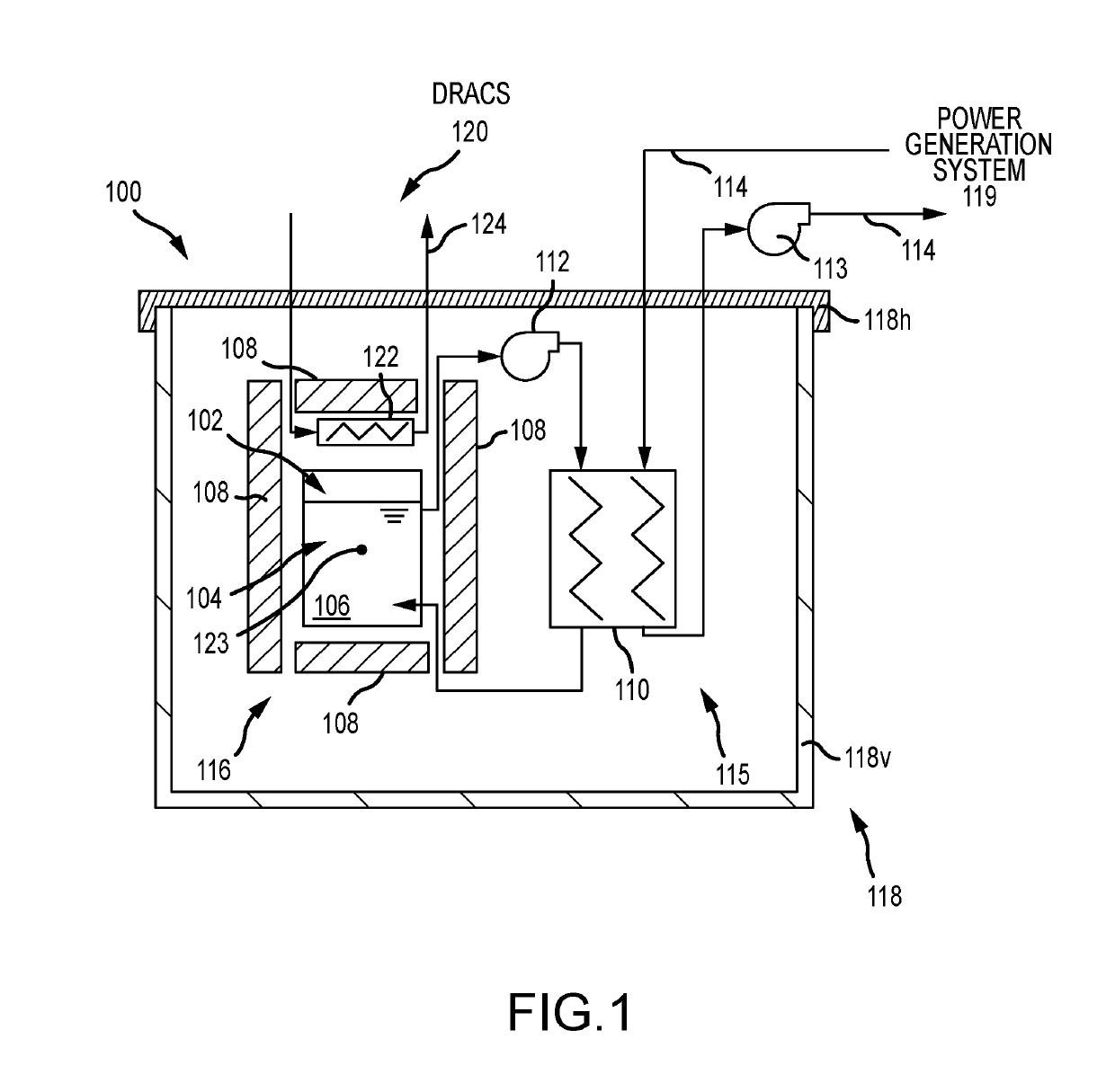
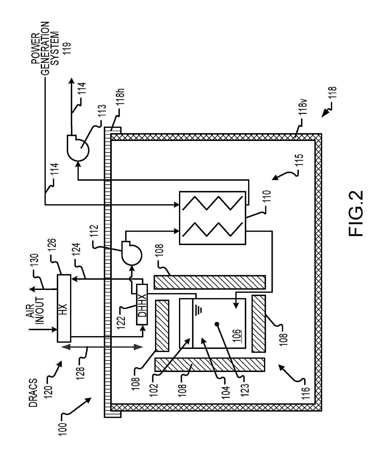
[0032]FIG. 1 illustrates, in a block diagram form, some of the basic components of a molten fuel reactor. In general, a molten fuel reactor 100 inc...


PUM


Abstract

A molten chloride fast reactor (MCFR) includes a plurality of reflectors defining a central core having a core geometric center. A flow channel fluidically connected to the central core. The flow channel includes an outlet flow channel downstream of the central core and an inlet flow channel upstream from the central core. A primary heat exchanger (PHX) disposed outside the central core and between the outlet flow channel and the inlet flow channel. The MCFR also includes a decay heat heat exchanger (DHHX). At least a portion of the DHHX is disposed above the core geometric center, and a fuel salt is configured to circulate at least partially through the outlet flow channel, the DHHX, the PHX, the inlet flow channel, and the central core.

Description

CROSS-REFERENCE TO RELATED APPLICATIONS[0001]The present application claims the benefit of U.S. Provisional Patent Application No. 62 / 624,646, titled “DIRECT HEAT EXCHANGER FOR MOLTEN CHLORIDE FAST REACTOR,” filed Jan. 31, 2018, the entire disclosure of which is incorporated by reference herein.STATEMENT REGARDING FEDERALLY SPONSORED RESEARCH OR DEVELOPMENT[0002]This invention was made with government support under DE-NE0008473 awarded by The Department of Energy. The government has certain rights in the invention.INTRODUCTION[0003]The utilization of molten fuels in a nuclear reactor to produce power provides significant advantages as compared to solid fuels. For instance, molten fuel reactors generally provide higher power densities compared to solid fuel reactors, while at the same time having reduced fuel costs due to the relatively high cost of solid fuel fabrication.[0004]Molten fluoride fuel salts suitable for use in nuclear reactors have been developed using uranium tetrafluo...

Claims


Application Information

Patent Timeline
IPC IPC(8): G21C3/44G21C19/04G21C19/28G21C7/30G21C1/22
CPCG21C3/44G21C19/04G21C19/28G21C7/30G21C1/22G21C1/03G21C1/326G21C3/54G21C11/06G21C15/18G21D1/006G21D1/04Y02E30/30Y02E30/00F22B37/00
Inventor ABBOTT, RYANCISNEROS, ANSELMO T.KRAMER, KEVINROECKER, JAMES A.WALTER, DANIEL J.WARDLE, KENT E.
Owner LLC TERRAPOWER
Why Eureka
Try Eureka