
Hydrogen compressor system

Inactive Publication Date: 2007-10-04
HITACHI LTD
View PDF9 Cites 14 Cited by
  • Summary
  • Abstract
  • Description
  • Claims
  • Application Information

AI Technical Summary

Benefits of technology

[0015]According to the present invention, hydrogen gas generated by a reformer can be supplied to both a compressor and high pressure tanks and the gas in the high pressure tanks can be supplied to initial or middle compressing stages, so that hydrogen generated by the reformer can be effectively used. Additionally, operating cost of a fuel cell vehicle using hydrogen as a fuel can be reduced. Further, operating efficiency of a hydrogen refueling station for supplying hydrogen to the fuel cell vehicle is enhanced. Excessive hydrogen is not exhausted, but recycled as much as possible and the amount of hydrogen which remains in the hydrogen tank can be reduced.

Problems solved by technology

However, the apparatus is not suitable for start and stop in a short period of time because it has a compressor and the like.
As a result, for example when the filling load to the fuel cell vehicle is low, a part of generated hydrogen gas becomes excessive and there is no choice but to wastefully burn the hydrogen gas or emit the hydrogen gas to the atmosphere without any treatment.
As a result, a larger amount of hydrogen is not supplied to the fuel cell vehicle and remains in the hydrogen tank, so that operating efficiency of the hydrogen tank is reduced.

Method used


Image

  • Hydrogen compressor system
  • Hydrogen compressor system
  • Hydrogen compressor system

Examples


Embodiment Construction

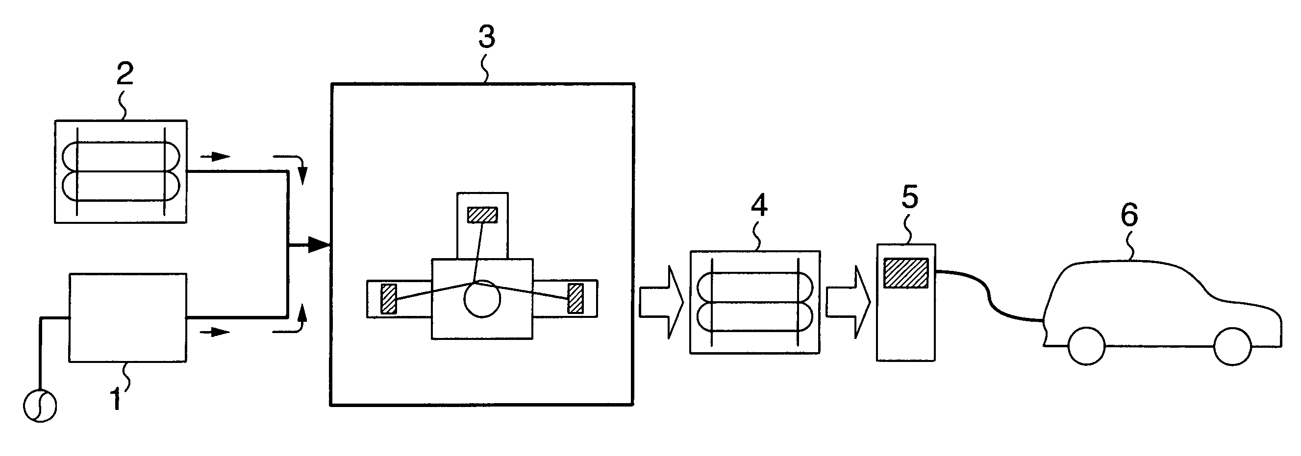
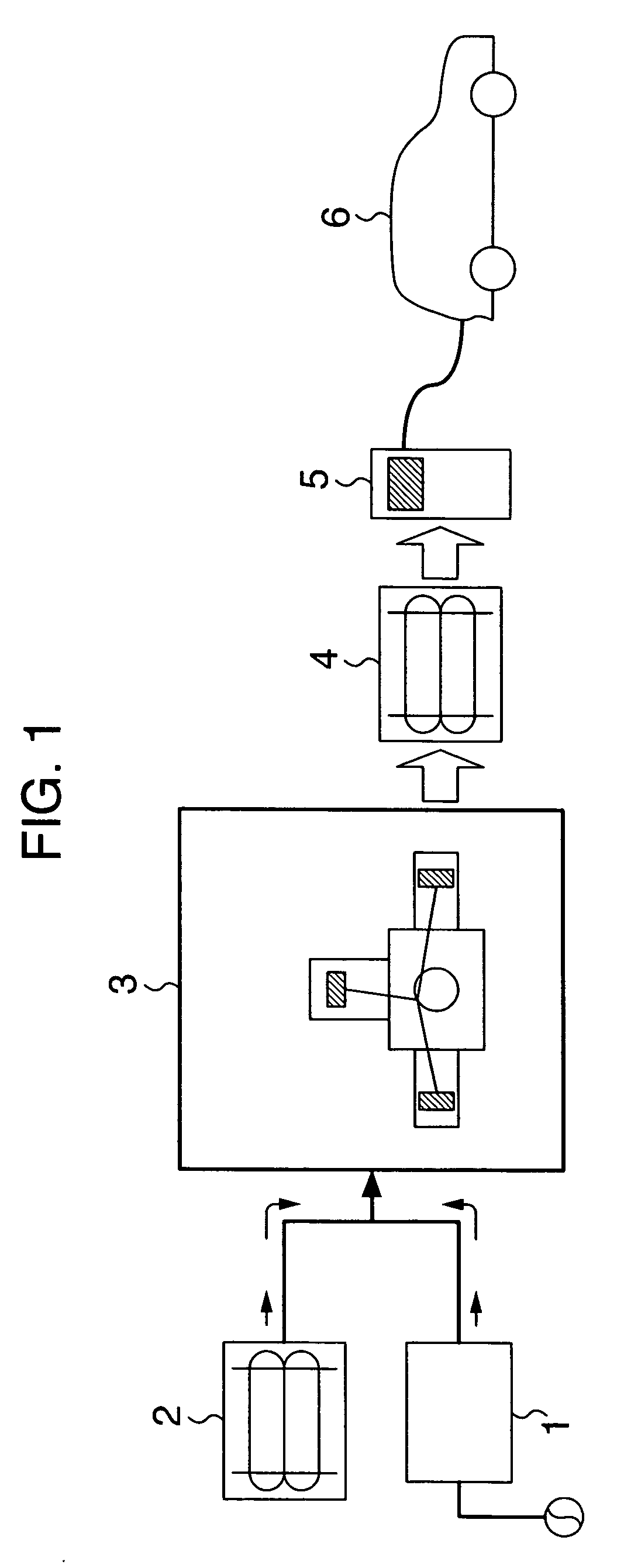
[0019]Now, one embodiment of a hydrogen refueling station according to the present invention will be described with reference to the drawings. FIG. 1 schematically shows a hydrogen refueling station 100 for supplying hydrogen, which is a fuel, to a fuel cell vehicle 6. Methods for supplying hydrogen gas to the fuel cell vehicle 6 include two types: on-site type and off-site type, as described above. In the on-site type, alcohol or petroleum fuel is reformed by a reformer 1 to obtain hydrogen fuel. Alternatively, pure hydrogen is generated by electrolysis of water, although it is not shown. In the hydrogen refueling station 100 comprising a hydrogen generating apparatus which generates pure hydrogen gas by means of the reformer 1 or the water electrolysis apparatus, pressure of generated hydrogen gas is about 0.6 MPa.

[0020]On the other hand, in the off-site hydrogen refueling station 100, pure hydrogen gas is extracted from by-product hydrogen or the like and sealed in a bomb 2 with ...


PUM

PropertyMeasurementUnit
Pressureaaaaaaaaaa
Pressureaaaaaaaaaa
Pressureaaaaaaaaaa

Abstract

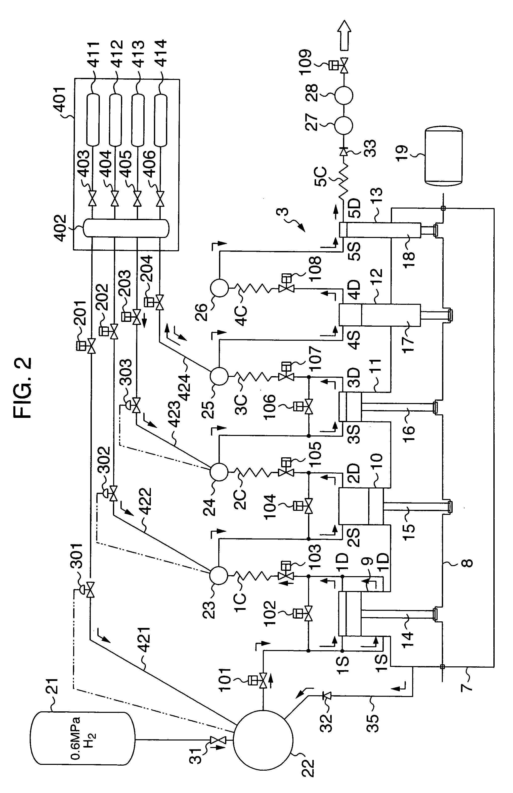
A hydrogen compressor system comprises a hydrogen generating apparatus for generating hydrogen gas to be supplied to a fuel cell vehicle and a multi-stage reciprocating compressor for pressurizing the hydrogen gas generated by the hydrogen generating apparatus. High pressure tanks having maximum use pressure of 20 MPa are connected to middle stages of the multi-stage reciprocating compressor by gas supplying lines via valves. By opening / closing the valves, hydrogen gas in the high pressure tanks can be selectively supplied to the middle stages of the multi-stage reciprocating compressor.

Description

BACKGROUND OF THE INVENTION[0001]The present invention relates to a hydrogen compressor system, more particularly a hydrogen compressor system suitable for use in a hydrogen refueling station for supplying hydrogen gas to a fuel cell vehicle.[0002]An example of a hydrogen refueling station for supplying hydrogen to a fuel cell vehicle is described in JP-A-2003-194297. The hydrogen refueling station described in JP-A-2003-194297 is a so-called on-site station in which hydrogen is obtained by electrolysis of water. In the on-site station, because pressure of generated hydrogen gas is about 0.6 MPa, a hydrogen compressor system for pressurization is required to supply hydrogen to the fuel cell vehicle. In JP-A-2003-194297, a hydrogen compressor is used to get higher pressure and the compressor is lubricated with water in order to avoid using of oil.[0003]Another example of the system for supplying hydrogen to a fuel cell vehicle is described in JP-A-2005-273811. A hydrogen supplying sy...

Claims


Application Information

Patent Timeline
IPC IPC(8): F17C5/06
CPCB60S5/02Y10T137/4807
Inventor KURITA, SHINICHIROARAI, SHIGERUAKANUMA, AKINORIFUKAI, YOUICHIROUMIURA, HARUO
Owner HITACHI LTD
Learn More