Steam Powered Turbine, Electric Power Regeneration System For A Vehicle

Inactive Publication Date: 2014-03-20
PROKOPICH BRENNAN MIKAEL
View PDF1 Cites 3 Cited by
  • Summary
  • Abstract
  • Description
  • Claims
  • Application Information

AI Technical Summary

Benefits of technology

[0009]It is a further object of the present invention to vastly reduce the operating costs that are typically associated with the use of an internal combustion engine by eliminating the need for expensive petroleum fuels.
[0010]It is a further object of the present invention to almost eliminate fuel emissions that are associated with the use of the internal comb

Problems solved by technology

Thus, undesirable vehicle emissions associated with the use of petroleum or coal products continue to be a worldwide problem.
Over the years to this

Method used


Image

  • Steam Powered Turbine, Electric Power Regeneration System For A Vehicle
  • Steam Powered Turbine, Electric Power Regeneration System For A Vehicle
  • Steam Powered Turbine, Electric Power Regeneration System For A Vehicle

Examples


Example

[0022]To make this description more clear, identical components having identical functions have been assigned with reference numerals.

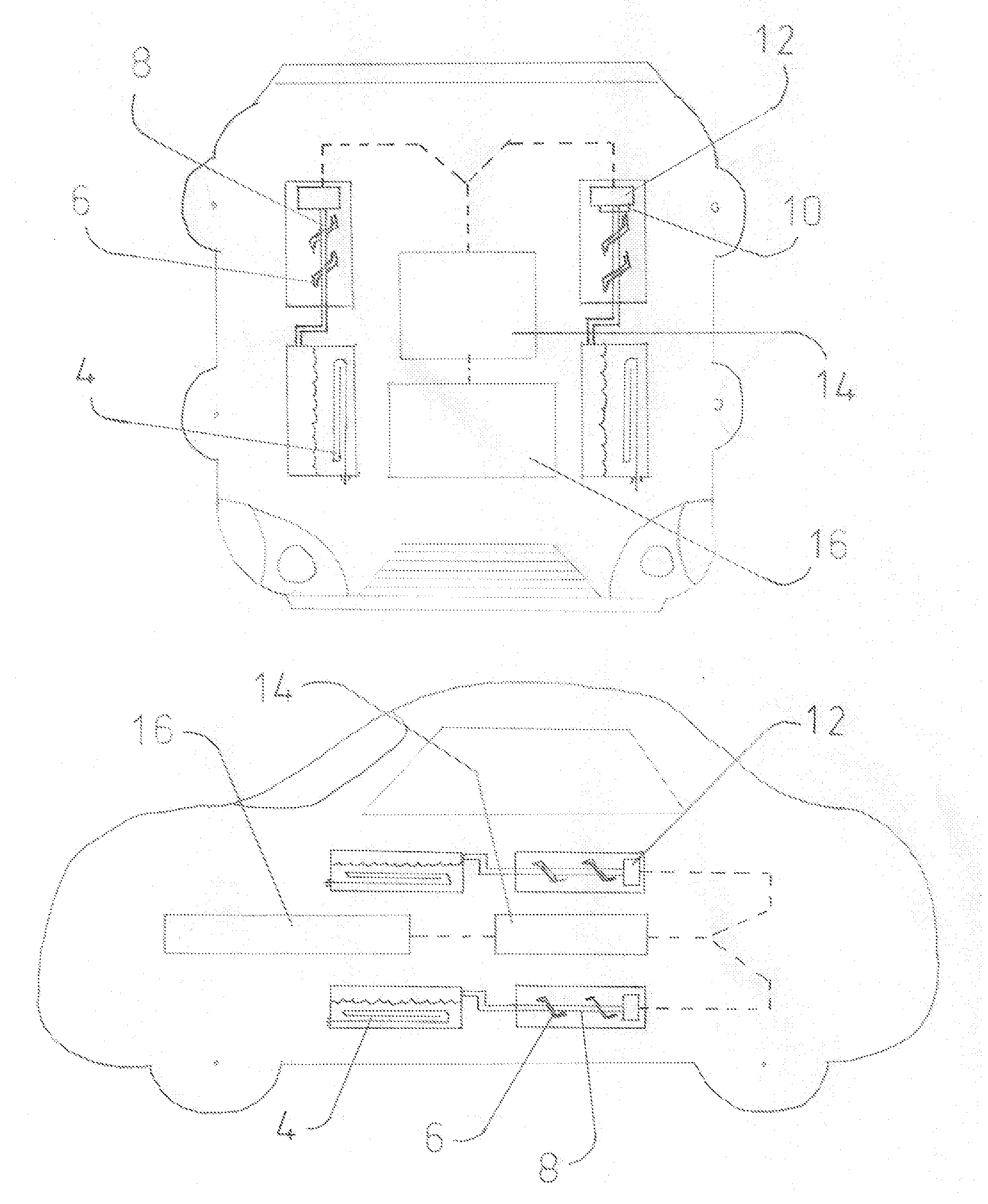
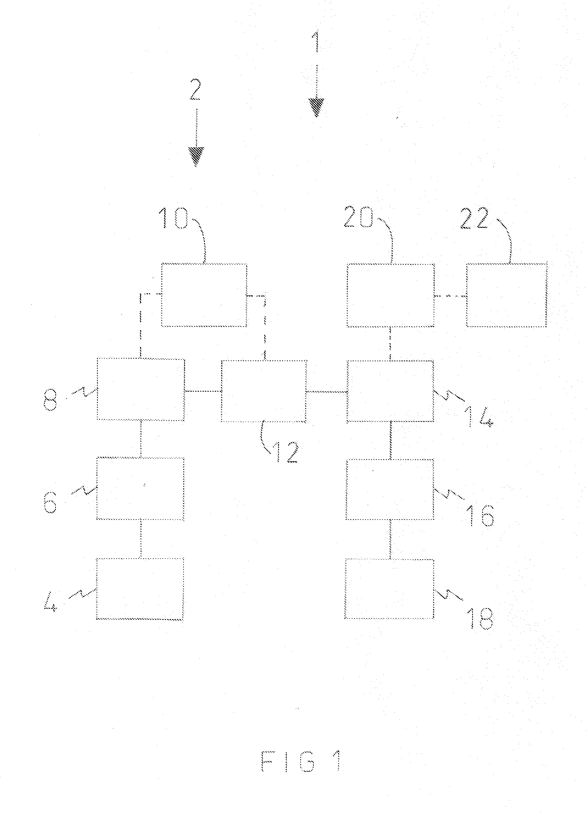
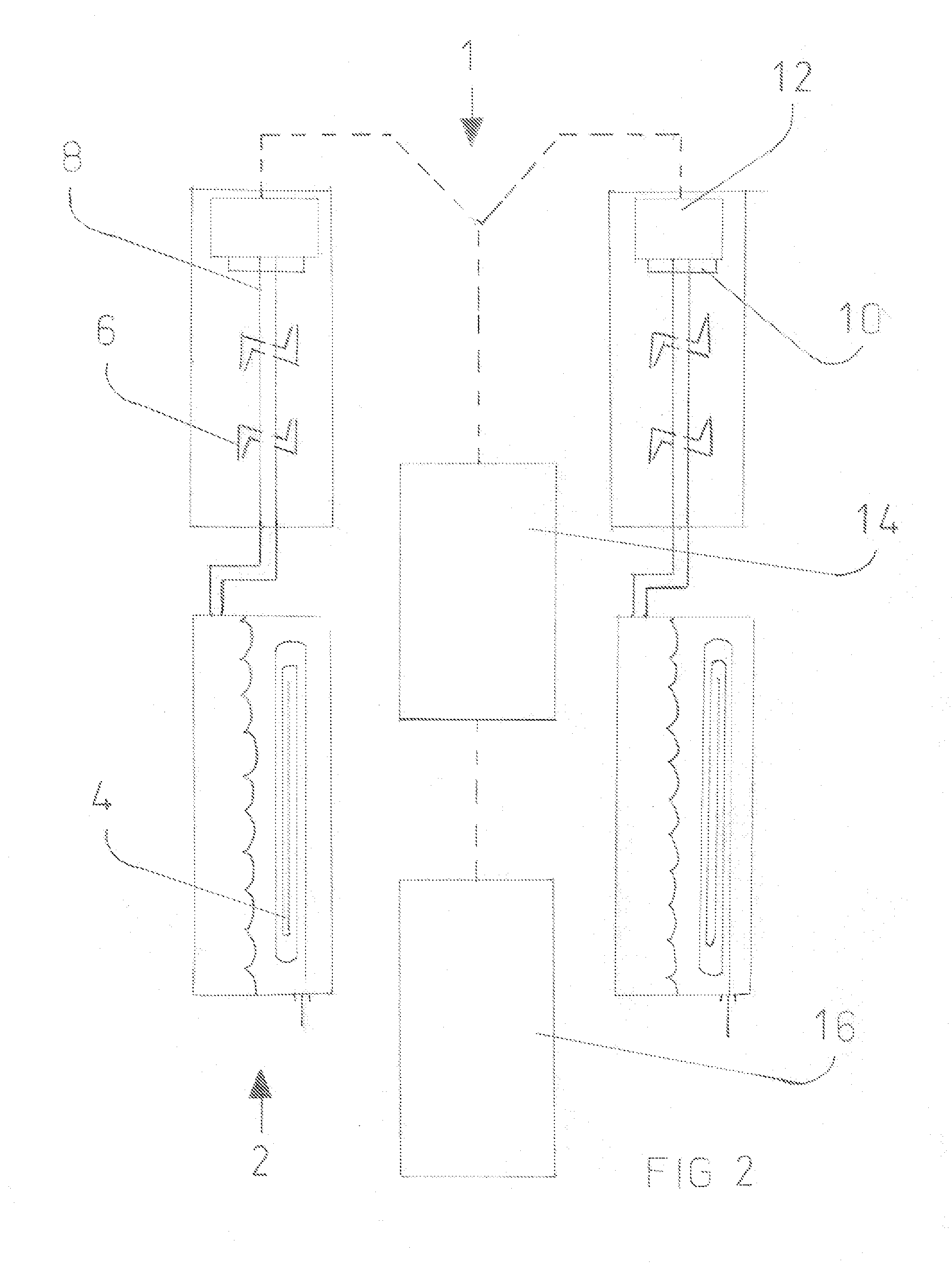
[0023]Refer to FIGS. 1-9 of the drawings illustrated therein is a steam power regeneration system which is designated #1 which is usable on a vehicle. The system designated #1 includes a steam generated turbine designated #2. Briefly the turbine includes at least one propeller designated #6 formed from a plurality of spouts, a rotor shaft designated #8, and mounted stabilizers for the rotor shaft designated #26. Attached at the end of at least one rotor shaft is a gear system designated #10 which may or may not be attached at the end of at least one rotor shaft mounted to the vehicle.

[0024]As it is known in the art, a steam current caused by a heating source designated #4 onto any element that will cause a steam enables the rotation of the at least one propeller #6 and subsequently causes a rotation of the rotor shaft #8 which enables the gear system ...


PUM


Abstract

The present invention provides a steam powered turbine battery regeneration system for a vehicle hay an electrically operable drive system. The system includes at least one battery which is mounted within such vehicle and is connected to such drive system and at least one steam powered turbine which is mounted within such vehicle and is electrically coupled to the at least one battery. The steam powered turbine has a propeller fixed in a vertical plane and affixed to a horizontally disposed shaft mounted within such vehicle. A rotational movement of the propeller caused by a flow of steam enables the at least one turbine to generate an electric energy which is stored in the at least one battery which is used by such drive system to move such vehicle in a direction of travel.

Description

FIELD OF THE INVENTION[0001]The present invention relates, in general, to a power regeneration system for vehicles and, more particularly, this invention relates to a steam power regeneration system for a vehicle which employs a steam operated turbine for generating electrical energy.BACKGROUND OF THE INVENTION[0002]As is generally known, vehicles for private, commercial and military either run on petroleum or coal products or on a combination of petroleum products and electric energy. The electric energy is generally used only on land vehicles wherein it can be generated of by rotating wheels. Thus, undesirable vehicle emissions associated with the use of petroleum or coal products continue to be a worldwide problem.[0003]Prior to the present invention, efforts have been made to eliminate use of petroleum or coal products. Over the years to this point, vehicles running on petroleum products or coal have left an overwhelmingly negative impression on earth with the emissions they lea...

Claims


Application Information

Patent Timeline
IPC IPC(8): H02K7/18
CPCH02K7/1823B60L2200/10B60L2200/12B60L2200/32B60L2200/34B60L2200/36B60L2200/40B60L2200/26Y02T10/70B60L50/11B60L50/66Y02T10/64Y02T10/7072
Inventor PROKOPICH, BRENNAN MIKAEL
Owner PROKOPICH BRENNAN MIKAEL
Why Eureka
Try Eureka