Method of manufacturing header tank for heat exchanger and heat exchanger having the header tank

Inactive Publication Date: 2008-05-29
DENSO CORP
View PDF1 Cites 27 Cited by
  • Summary
  • Abstract
  • Description
  • Claims
  • Application Information

AI Technical Summary

Benefits of technology

[0013]As another example, the first engagement portion is formed on the core plate, and a portion of the first wall portion is bent outwardly along a bending axis with the first engagement portion to be in a pre-bent condition. After the tank body is placed on the base portion, the portion of the first wall portion is moved toward the tank body about the bending axis such that the first engagement portion engages with the tank body. In this case, the bending axis is included within the first wall portion, and the portion of the first engagement portion is moved t

Problems solved by technology

In such a heat exchanger, because pipe members, such as inlet pipe and outlet pipe, for introducing and discharging an internal fluid, are coupled to the tank body, the engagement portions will interfere in the pipe members during the bending of the side wall portions.
In such a case, it will be difficult to properly bend the side w

Method used


Image

  • Method of manufacturing header tank for heat exchanger and heat exchanger having the header tank
  • Method of manufacturing header tank for heat exchanger and heat exchanger having the header tank
  • Method of manufacturing header tank for heat exchanger and heat exchanger having the header tank

Examples


first embodiment

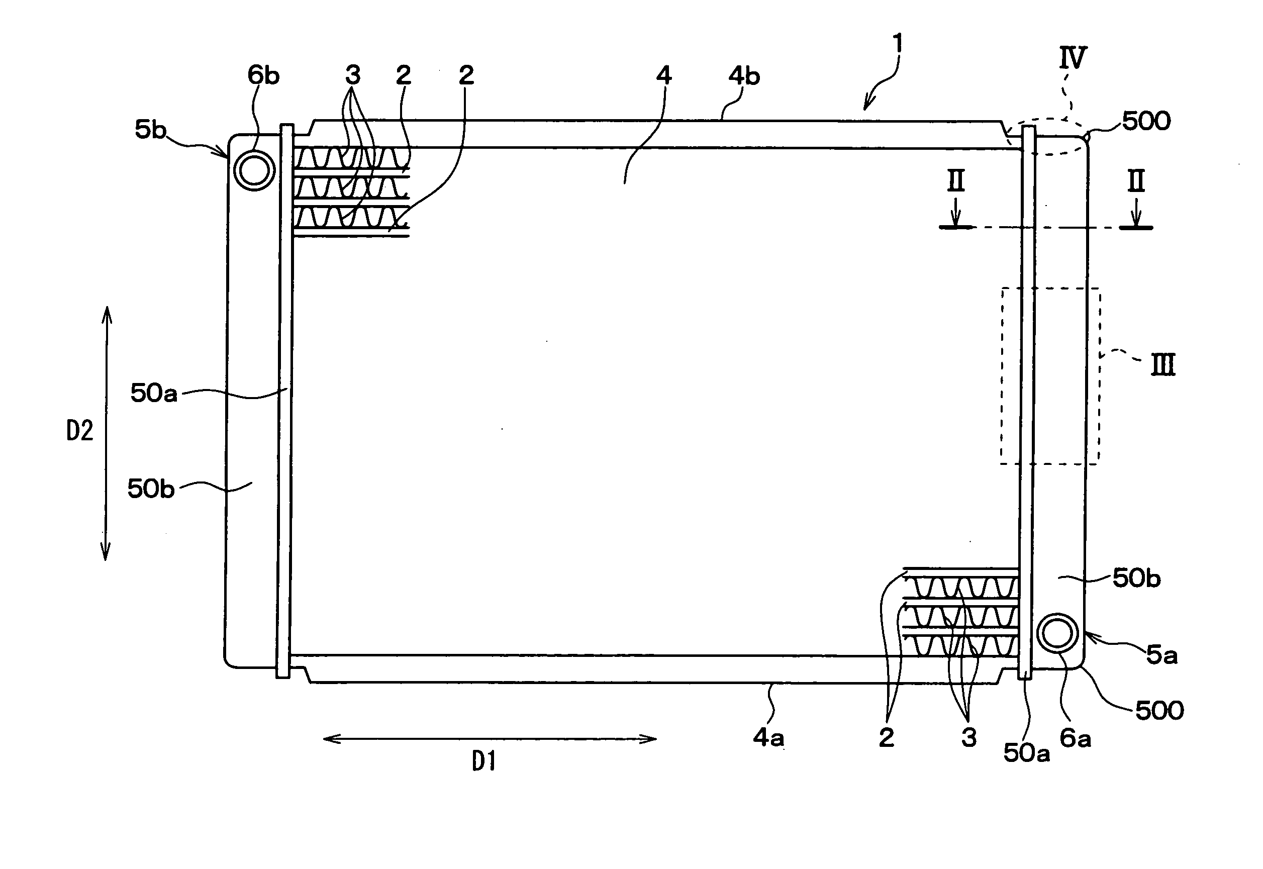
[0046]FIG. 1 shows a heat exchanger 1 of the first embodiment when viewed along a flow direction of air. The heat exchanger 1 is exemplarily employed to a radiator that is generally mounted in an engine compartment of a vehicle and performs heat exchange between an engine coolant and the air, the flow of which is for example generated by a blower, thereby to cool the engine coolant.

[0047]The radiator 1 generally includes tubes 2, fins 3, side plates 4a, 4b and header tanks 5a, 5b. The tubes 2 have generally flat tubular shapes, and form passages therein for allowing the engine coolant, which flows out from the engine, to pass through. The tubes 2 are, for example, made of light metals having high heat conductivity. In the present embodiment, the tubes 2 are exemplarily made of aluminum alloy. Also, the tubes 2 are formed of clad members, at least one of surfaces of which is coated with a filler material, such as a brazing material.

[0048]The fins 3 are joined to outer surfaces of the...

second embodiment

[0101]In the radiator 1 of the second embodiment, the core plate 50a has a shape slightly different from the core plate 50a of the radiator 1 of the first embodiment.

[0102]In a case that the tank body 50b and the core plate 50a are made of different materials, such as aluminum alloy and resin, the tank body 50b has a coefficient of linear expansion greater than that of the core plate 50a. Under a high temperature condition, the end wall portions 52c, 52d will be deformed by being pressed by the projected end 600 in the tank longitudinal direction D2 due to thermal expansion of the tank body 50b.

[0103]In the second embodiment, therefore, the core plate 50a includes support wall portions 610 for supporting the end wall portions 52c, 52d, as shown in FIGS. 12, 13A and 13B. The support wall portions 610 project from the lengthwise edges of the bottom wall portion 51, at positions adjacent to the longitudinal ends of the core plate 50a. In addition, the support wall portions 610 connect...

third embodiment

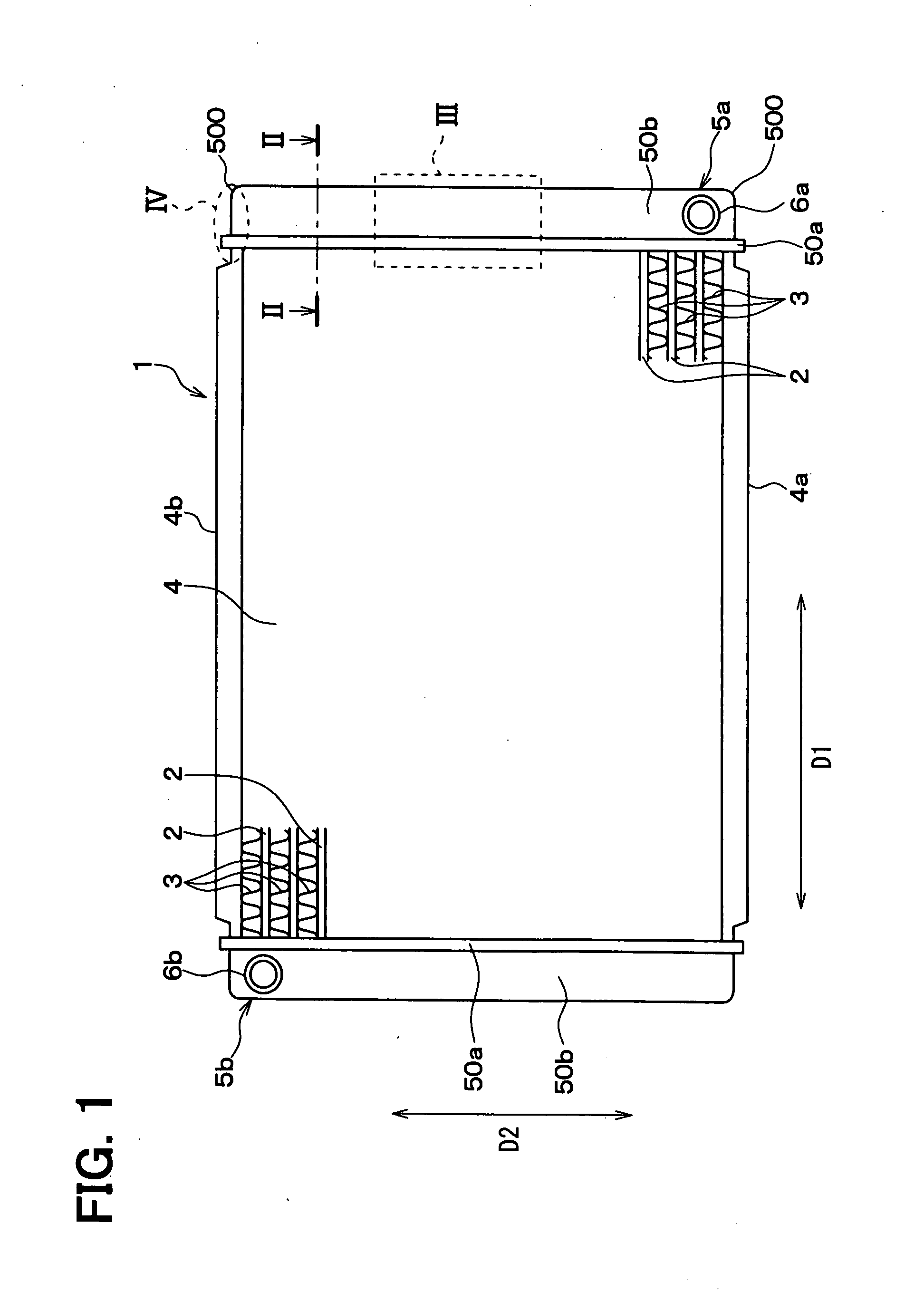
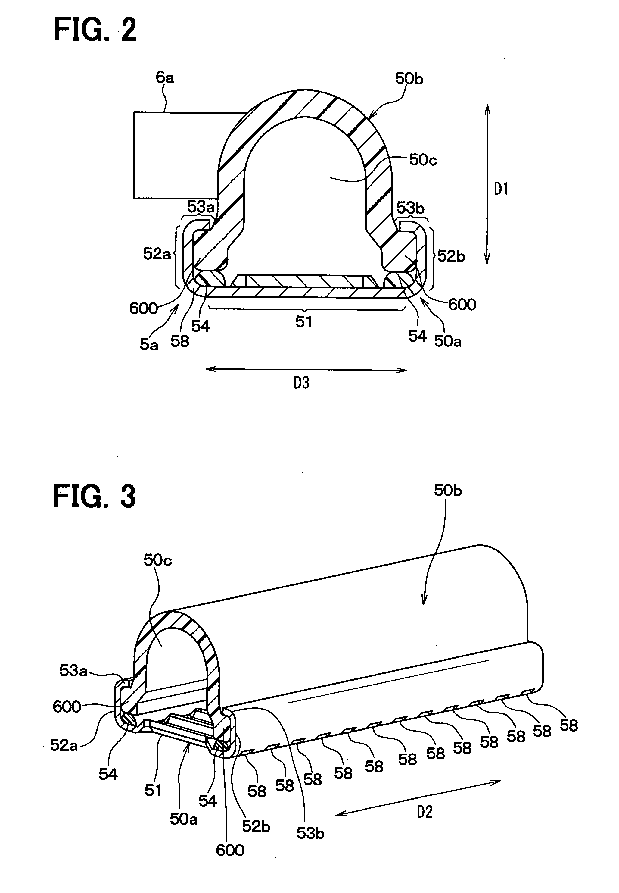
[0106]In the core plate 50a of the radiator 1 of the first embodiment, each of the side engagement portions 53a, 53b forms a generally right angle with the corresponding side wall portion 52a, 52b, as shown in FIG. 2. However, the angle between the side engagement portion 53a, 53b and the side wall portion 52a, 52b can be modified.

[0107]In the radiator 1 of the third embodiment, each side engagement portion 53a, 53b is engaged with the projected end 600 such that an angle +1 between the side engagement portion 53a, 53b and the side wall portion 52a, 52b is smaller than 90 degrees, as shown in FIG. 15. Therefore, an engagement force, that is, a force for joining the tank body 50b with the core plate 50a improves. Further, the sealing effect of the sealing member 54 improves.

[0108]The above engagement structure may be also employed to the end engagement portions 53c, 53d. That is, the end engagement portions 53c, 53d may be engaged with the projected end 600 such that the angle betwee...


PUM

PropertyMeasurementUnit
Angleaaaaaaaaaa
Angleaaaaaaaaaa
Widthaaaaaaaaaa

Abstract

A method of manufacturing a header tank for a heat exchanger includes forming a first engagement portion in a core plate, placing a tank body relative to a base portion of the core plate, and moving a first wall portion toward the tank body such that the first engagement portion is engaged with the tank body. In the forming, a portion of the core plate is bent, the portion extending from the first wall portion. In the placing, the tank body is placed such that an opening of the tank body is covered by the base portion such that a tank inner space is defined. The first engagement portion is engaged with the tank body by moving the first wall portion toward the tank body.

Description

CROSS REFERENCE TO RELATED APPLICATION[0001]This application is based on Japanese Patent Applications No. 2006-321389 filed on Nov. 29, 2006 and No. 2007-104600 filed on Apr. 12, 2007, the disclosures of which are incorporated herein by reference.FIELD OF THE INVENTION[0002]The present invention relates to a method of manufacturing a header tank for a heat exchanger and a heat exchanger having the header tank.BACKGROUND OF THE INVENTION[0003]In general, a heat exchanger such as a radiator has tubes and a header tank. The header tank is, for example, constructed of a tank body having a semi-tubular shape and a core plate to which the tubes are coupled. The core plate is, for example, fixed to the tank body through engagement portions. A heat exchanger having such a structure is described in Japanese Unexamined Patent Publications No. 2004-66283 and No. 2002-286396 (U.S. Pat. No. 6,892,804), for example.[0004]In the heat exchanger disclosed in the Publication No. 2004-66283, a core pl...

Claims


Application Information

Patent Timeline
IPC IPC(8): F28F9/02B21D53/02
CPCB21D53/02Y10T29/4935F28F2275/122F28F9/0226
Inventor HAKAMATA, OSAMUOZAKI, TATSUONINAGAWA, TOSHIHIDE
Owner DENSO CORP
Why Eureka
Try Eureka