Engine hood for construction machine

a construction machine and engine technology, applied in mechanical machines/dredgers, wing accessories, transportation and packaging, etc., can solve the problems of a burden on the operator, a short service life, and a remarkable inefficiency in the performance of a work

a construction machine and engine technology, applied in mechanical machines/dredgers, wing accessories, transportation and packaging, etc., can solve the problems of a burden on the operator, a short service life, and a remarkable inefficiency in the performance of a work

US8646556B2Inactive Publication Date: 2014-02-11KOMATSU LTD

Image

  • Engine hood for construction machine
  • Engine hood for construction machine
  • Engine hood for construction machine

Examples


Embodiment Construction

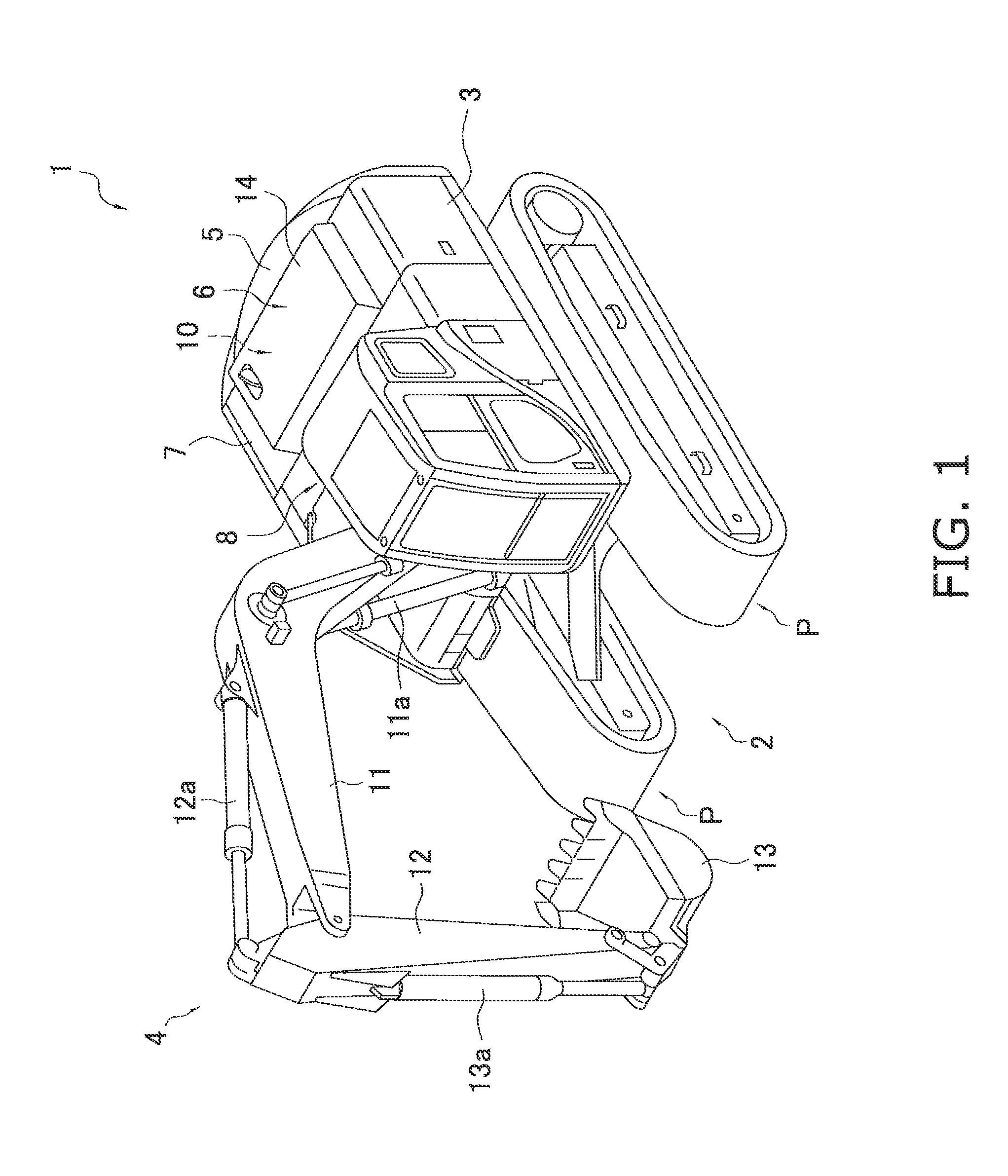
[0039]A hydraulic excavator (construction machine) 1, employing an engine hood according to an exemplary embodiment of the present invention, will be hereinafter explained with reference to FIGS. 1 to 12(b).

Hydraulic Excavator 1

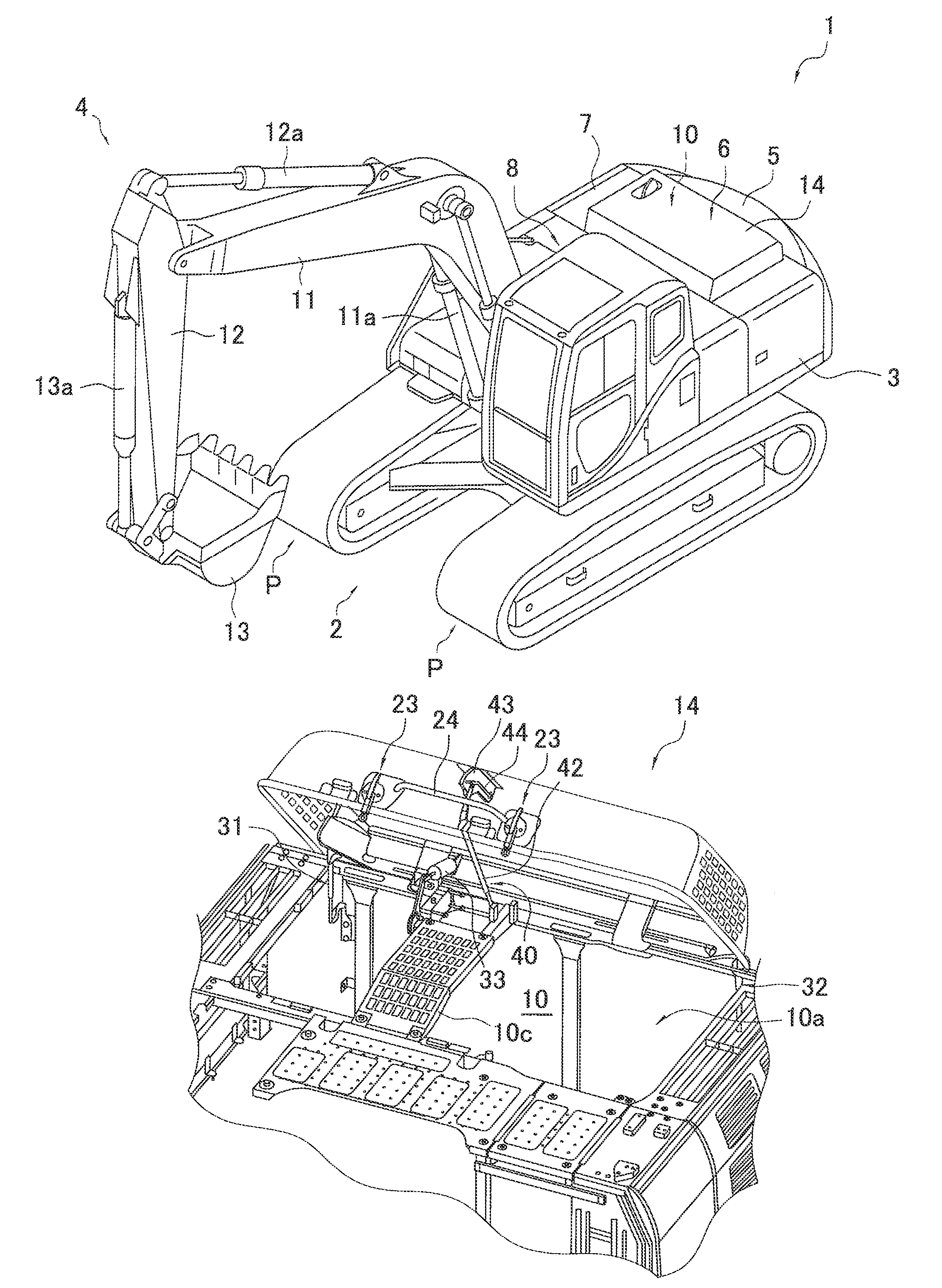
[0040]As illustrated in FIG. 1, the hydraulic excavator 1 according to the present exemplary embodiment includes a lower travelling unit 2, a revolving unit 3, a work implement 4, a counterweight 5, a vehicle body 6, a machine compartment 7 and a cab 8.

[0041]The lower travelling unit 2 moves the hydraulic excavator 1 back and forth by circulating a pair of crawler bents P wrapped about the both end portions thereof arranged right and left in a travel direction. Further, the revolving unit 3 is mounted on the top surface of the lower travelling unit 2.

[0042]The revolving unit 3 can revolve in arbitrary directions with respect to the lower travelling unit 2. Further, the work implement 4, the counterweight 5, the vehicle body 6 and the cab 8 are mounted on the ...


PUM


Abstract

An engine hood for a construction machine is configured to be pivoted in a vehicle body back-and-forth direction about a hinge attached as a pivot center to a longitudinal side part of a counterweight. The engine hood includes an engine hood main body, a first operating force applying unit and a second operating force applying unit. The engine hood main body is attached to a vehicle body of the construction machine in a pivotably openable / closable state. The first operating force applying unit is configured to apply force in a direction of opening the engine hood main body until the engine hood main body reaches a vicinity of a predetermined opening angle. The second operating force applying unit is configured to apply force in a direction of closing the engine hood main body when the engine hood main body is pivoted at the predetermined opening angle or greater.

Description

CROSS-REFERENCE TO RELATED APPLICATIONS[0001]This application claims priority to Japanese Patent Application No. 2010-014288 filed on Jan. 26, 2010, the disclosure of which is hereby incorporated herein by reference in its entirety.TECHNICAL FIELD[0002]The present invention relates to an engine hood mounted to a vehicle body of a construction machine such as a hydraulic excavator.BACKGROUND ART[0003]In recent years, construction machines have generally employed a structure that a power compartment accommodating a power source and etc. is covered with an exterior cover for blocking out noise generated in the power compartment.[0004]Meanwhile, regular maintenance checks are required for the power source accommodated within the power compartment covered with the exterior cover, and in some instances, an urgent maintenance work and etc. may be required for the power source. In such cases, it is remarkably inefficient to perform a work, for instance, by detaching the exterior cover fixed...

Claims


Application Information

Patent Timeline
11 Feb 2014
Publication
US8646556B2
IPC
B62D25/10
CPC
E02F9/0891; E05F1/1091; E05Y2201/412; E05Y2201/478; E02F3/32; E05Y2900/518; E05Y2800/21; E05Y2201/424
Inventors
SHIMADA, YOSHIAKI; TSUJIMOTO, NAOKI