Mode-locked laser method and apparatus

Active Publication Date: 2005-06-02
CONTINUUM ELECTRO OPTICS +1
View PDF3 Cites 10 Cited by
  • Summary
  • Abstract
  • Description
  • Claims
  • Application Information

AI Technical Summary

Benefits of technology

[0007] In an exemplary embodiment, the present invention provides an apparatus and method for maintaining a mode-locked laser in a mode-locked condition by adjusting the optical length of the laser cavity in accordance with the temporal behavior of the pulse train profile. More specifically, it has been observed that when a laser is out of mode-lock, the pulse train will exhibit a significant level of noise which is not present when it is in a mode-locked condition. Furthermore, a first characteristic noise will be observed if the optical length of the laser cavity is longer than the optimal length for mode-lock (at a desired pulse repetition frequency), whereas a se

Problems solved by technology

More specifically, it has been observed that when a laser is out of mode-lock, the pulse train wil

Method used


Image

  • Mode-locked laser method and apparatus
  • Mode-locked laser method and apparatus
  • Mode-locked laser method and apparatus

Examples


Example

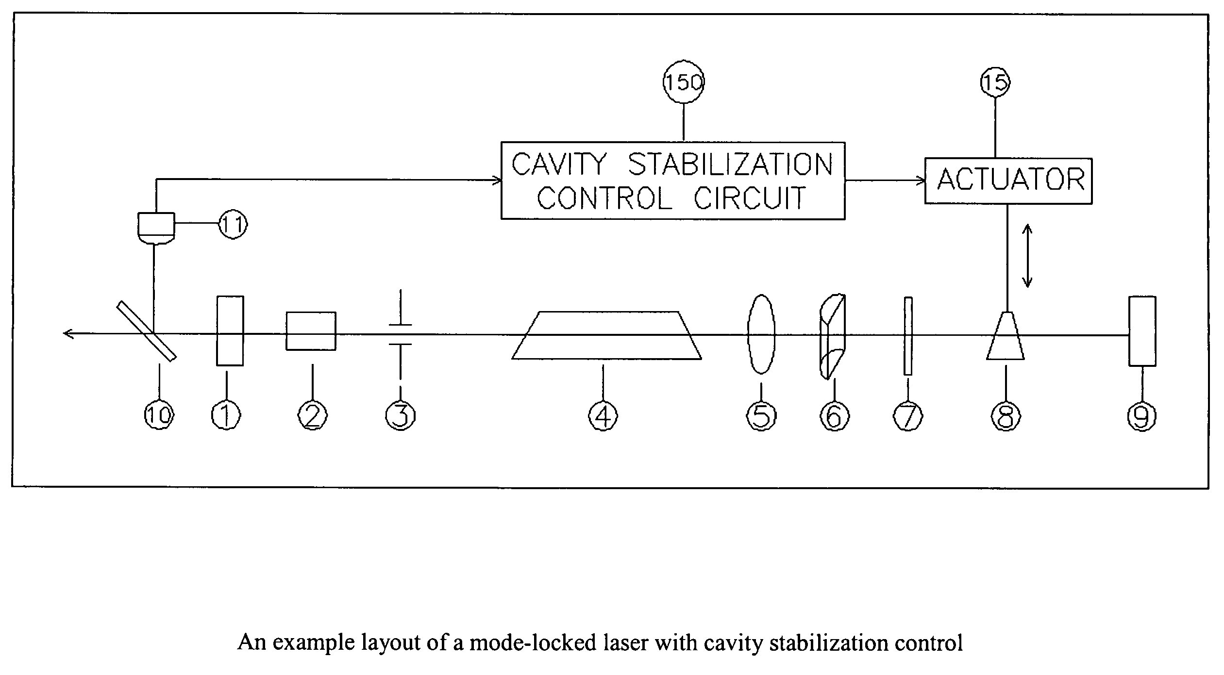
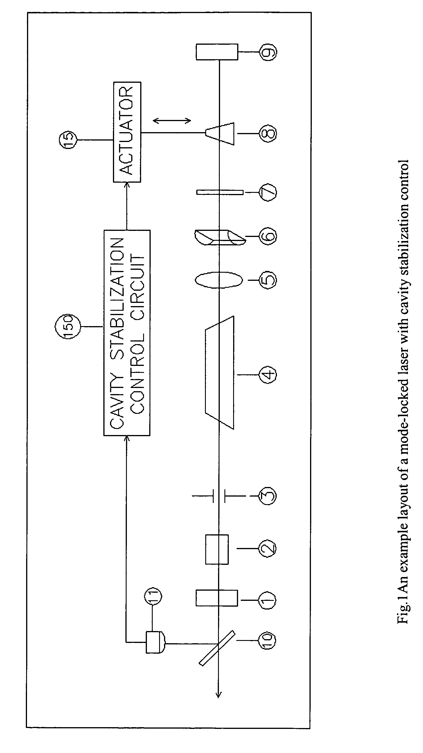
[0014]FIG. 1 shows an exemplary embodiment of a mode-locked laser 100 in accordance with the present invention. The laser 100 includes a stabilization circuit 150 which will be described in greater detail below.

[0015] The laser 100 includes an output coupler mirror 1, a mode locker 2, a transverse mode limit aperture 3, a Nd:YLF crystal 4, a spherical lens 5, a cylindrical lens 6, an etalon 7, a variable thickness polarizer 8, a highly reflective cavity mirror 9, and a beam sampling mirror 10. These elements are arranged along the beam path of the laser cavity.

[0016] A sensor 11 monitors the laser beam generated by the laser 100 via a beam sampling mirror 10. The sensor 11 is coupled to the stabilization circuit 150.

[0017] The stabilization circuit 150 controls an actuator 15 which moves the variable thickness polarizer 8 in a direction transverse to the beam path. The polarizer 8, which has an index of refraction different from air, has a tapered cross-section so that a transver...


PUM


Abstract

A method and apparatus for stabilizing the output of a mode-locked laser by monitoring the temporal behavior of the pulse train profile and controlling the laser cavity optical length and/or loss modulation frequency accordingly. A mismatch of the cavity optical length and the loss modulation frequency will yield a first characteristic noise condition on the laser beam pulse train when the optical length is too short for a given loss modulation frequency and a second, different noise condition when the optical length is too long. The laser beam is monitored and analyzed to determine which noise condition is present. The cavity optical length is adjusted accordingly by movement of one or more optical elements or by changing the index of refraction of one or more optical elements. In the alternative, or additionally, the loss modulation frequency can be adjusted to bring the laser back into mode lock.

Description

RELATED APPLICATIONS [0001] The present application claims priority from U.S. Provisional Patent Application No. 60 / 526,224, filed on Dec. 1, 2003, and which is herein incorporated by reference in its entirety.FIELD OF THE INVENTION [0002] The present invention relates to mode-locked lasers, particularly to methods and apparatus for achieving mode-lock with high stability. BACKGROUND INFORMATION [0003] High stability mode-locked lasers are of importance for research and industrial applications, among others. In order for such a laser to be mode-locked, the cavity length of the laser must be matched to the frequency of the loss modulator (e.g., an acousto-optic modulator) of the laser. The loss modulation frequency of the laser corresponds to the pulse repetition frequency. This matched condition can be expressed as follows: f=c / (2*L),   (Eq. 1) where f is the loss modulation frequency of the mode-lock pulse train, c is the speed of light, and L is the optical path length of the las...

Claims


Application Information

Patent Timeline
IPC IPC(8): H01SH01S3/00H01S3/08H01S3/098H01S3/106H01S3/13H01S3/136H01S3/139
CPCH01S3/08H01S3/08045H01S3/1068H01S3/139H01S3/1305H01S3/136H01S3/1109
Inventor XU, FAMINGFU, QIANGROGERS, BRIANCHEN, ZHENGYUHU, WENTAO
Owner CONTINUUM ELECTRO OPTICS
Why Eureka
Try Eureka