Image information recording/readout method and apparatus

a technology of image information and recording method, applied in the field of image recoding/readout method and apparatus, can solve the problems of so-called photovoltaic noise, large source of etc., and achieve the effects of reducing and stabilizing photovoltaic noise, dark latent image noise, and high voltage application history nois

Inactive Publication Date: 2008-05-15
FUJIFILM CORP
View PDF3 Cites 2 Cited by
  • Summary
  • Abstract
  • Description
  • Claims
  • Application Information

AI Technical Summary

Benefits of technology

[0027]As described above, when the preliminary processing is performed at least once in every 60 seconds or less, advantageous effects of reducing and stabilizing photovoltaic noise, dark latent image noise, and high voltage application history noise may be obtained. It is preferable, however, that the preliminary processing be performed once in every 30 seconds or less, and more preferably once in every 10 seconds or less in order to obtain more significant noise reduction and stabilization effects.
[0028]The image information recording / readout apparatus of the present invention is an apparatus for recording and reading out image information using an electrostatic recorder including the following stacked in the order listed below: a first electrode layer; a photoconductive layer that shows conductivity by receiving a recording electromagnetic wave representing image information; and a second electrode layer, with a storage section formed between the first and second electrode layers for storing an amount of charges in proportion to an amount of energy of the electromagnetic wave as latent image charges, in which the image information is recorded in the storage section as an electrostatic latent image when the recording electromagnetic wave is irradiated on the first electrode layer with a recording voltage being applied between the electrode of the first electrode layer and the electrode of the second electrode layer, and image information proportional to the latent image charges is read out with the first and second electrode layers being maintained at the same potential, the apparatus including:
[0029]a voltage application means for applying a predetermined voltage between the electrode of the first electrode layer and the electrode of the second electrode layer;
[0030]an erasing light irradiation means for irradiating erasing light on the photoconductive layer; and
[0031]a control means for controlling the voltage application means and the erasing light irradiation means such that a preliminary processing is performed regularly during an intermission between recordings of image information, in which voltage application for applying a voltage of predetermined magnitude and polarity between the electrode of the first electrode layer and the electrode of the second electrode layer for a predetermined time, and light irradiation for irradiating erasing light on the photoconductive layer with the first and second electrode layers being maintained at the same potential are performed.
[0032]In the image information recording / readout apparatus described above, if the control means is a means for causing the preliminary processing to be performed once in every 60 seconds or less, advantageous effects of reducing and stabilizing photovoltaic noise, dark latent image noise, and high voltage application history noise may be obtained. Here, if the control means is a means for causing the preliminary processing to be performed preferably once in every 30 seconds or less, and more preferably once in every 10 seconds or less, more significant noise reduction and stabilization effects may be obtained.

Problems solved by technology

This causes currents to flow, even when the dose of recording light is in the range of 0 mR, by the irradiation of readout light, posing a problem of so-called photovoltaic noise.
Continued use of the electrostatic recorder causes the photovoltaic noise to show local dependency, which leads to a problem of artifact.
Thus, the dark latent image caused by the high level dark current immediately after the voltage application is a large source of noise when a readout operation is performed.
Still further, the amount of dark latent image changes with the time from the application of the voltage to the irradiation of the recording radiation and usage history, so that it is difficult to correct image data not to appear the dark latent image noise on the reproduced image.
In addition, as a result of short-circuiting of the electrodes prior to the readout operation, a new electric field is formed through voltage application (generally, high voltage) and short-circuiting, and light (readout light) is irradiated under the new electric field, which poses a problem of high voltage application history noise to be generated.
The high voltage application history noise also changes with time and usage history, it is difficult to correct image data not to appear the high voltage application history noise on the reproduced image, like the dark latent image noise described above.
Further continued use of the electrostatic recorder causes the high voltage application history noise to show local dependency, like the photovoltaic noise, which leads to a problem of artifact.
It has been recognized, however, that the method described in U.S. Pat. No. 6,373,063 is unable to sufficiently reduce the photovoltaic noise, dark latent image noise, and high voltage application history noise, and image quality is degraded even if the voltage application and erasing light irradiation are performed in the case in which a recording of image information is performed after the voltage application and erasing light irradiation are performed, then the application of the voltage to the electrostatic recorder is stopped for a while, and a recording of image information is performed again.

Method used


Image

  • Image information recording/readout method and apparatus
  • Image information recording/readout method and apparatus
  • Image information recording/readout method and apparatus

Examples


Embodiment Construction

[0038]Hereinafter, an embodiment of the present invention will be described in detail with reference to the accompanying drawings.

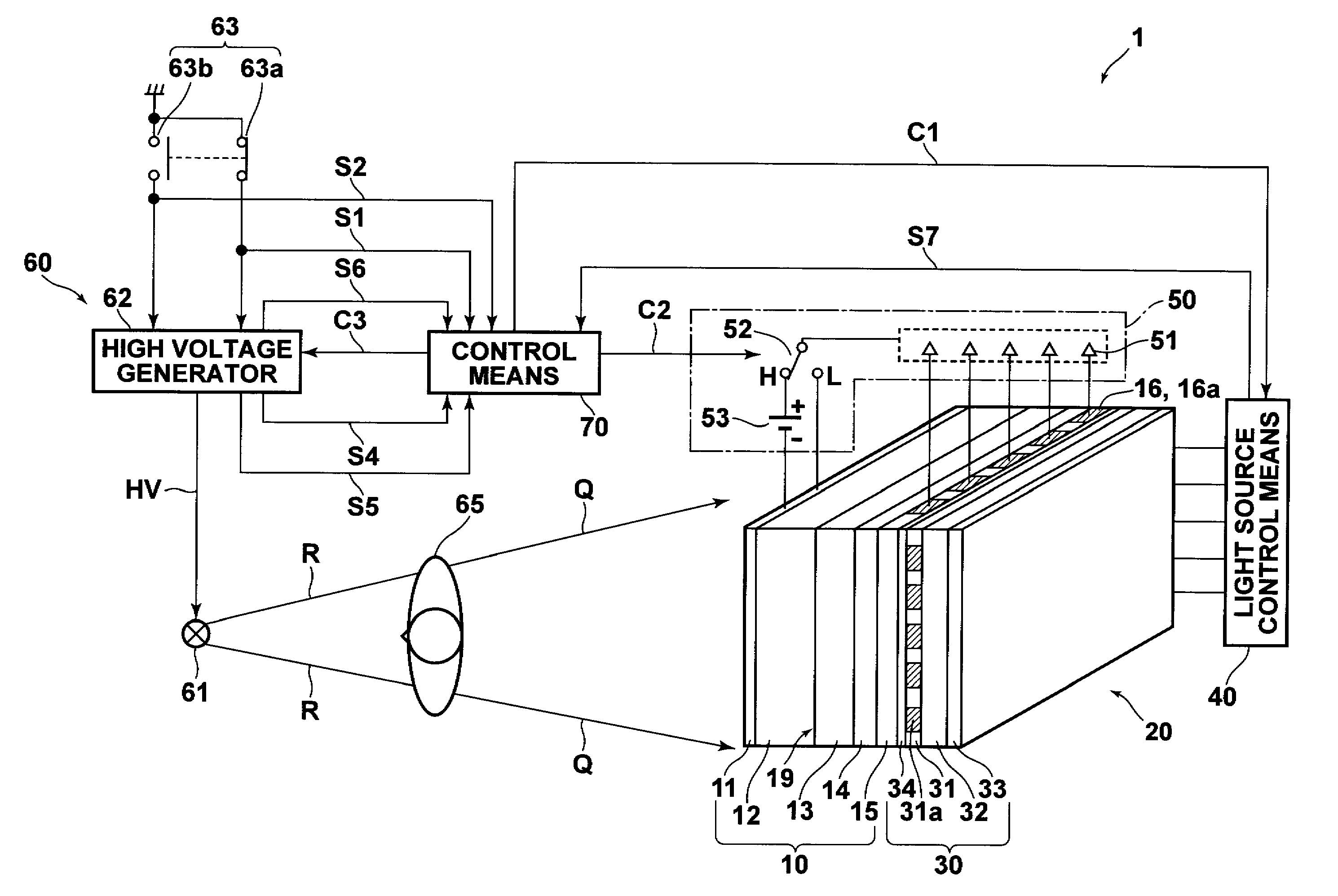
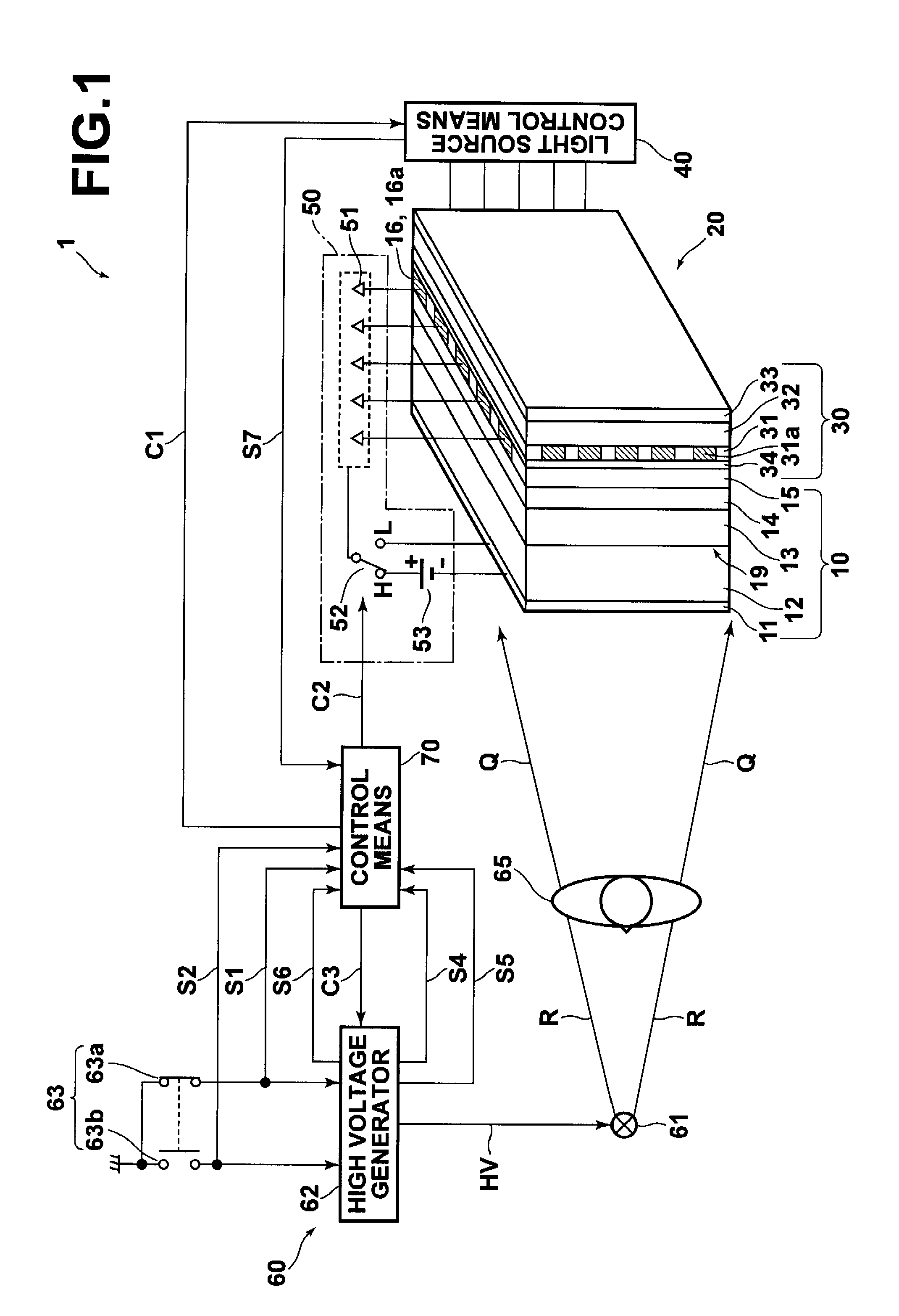
[0039]FIG. 1 is a schematic view of a radiation image recording / readout apparatus to which the image information recording / readout method and apparatus of the present invention are applied.

[0040]As illustrated in FIG. 1, the radiation image recording / readout apparatus 1 includes: a solid state radiation detector (also simply referred to as “detector”) 10, as an electrostatic recorder; a planar light source 30 stacked on the detector 10; a readout unit 20 including a light source control means 40 for controlling the planar light source 30 and a current detection circuit 50 for reading out charges from the detector 10; a radiation irradiation unit 60; and a control means 70 connected to the current detection circuit 50 and radiation irradiation unit 60.

[0041]The detector 10 generates charges in a recording photoconductive layer 12 when recording radiation (...


PUM

PropertyMeasurementUnit
timeaaaaaaaaaa
timeaaaaaaaaaa
wavelengthaaaaaaaaaa

Abstract

In order to reduce and stabilize photovoltaic noise, dark latent image noise, and high voltage application history noise, a preliminary processing is performed regularly during an intermission between recordings of image information, in which voltage application for applying a voltage of predetermined magnitude and polarity between the electrode of the first electrode layer and the electrode of the second electrode layer for a predetermined time, and light irradiation for irradiating erasing light on the photoconductive layer with the first and second electrode layers being maintained at the same potential are performed.

Description

BACKGROUND OF THE INVENTION[0001]1. Field of the Invention[0002]The present invention relates to an image recoding / readout method and apparatus for recording image information in an electrostatic recorder as an electrostatic latent image, and reading out the recorded electrostatic latent image.[0003]2. Description of the Related Art[0004]In medical X-ray imaging and the like, an image recording / readout system that uses an X-ray sensitive photoconductor such as, for example, a selenium plate formed of a-Se (amorphous selenium) as an electrostatic recorder (photoreceptor, solid state radiation detector) in order to reduce radiation dose received by the subject and to improve diagnostic performance. In the system, recording radiation, such as X-ray representing radiation image information is irradiated on the electrostatic recorder to store latent image charges representing the radiation image information in the storage section of the electrostatic recorder, thereafter currents generat...

Claims


Application Information

Patent Timeline
Patent Type & Authority Applications(United States)
IPC IPC(8): G03G15/05
CPCG03G21/08
Inventor OGAWA, MASAHARU
Owner FUJIFILM CORP
Why Eureka
Try Eureka