
Operational amplifier

Active Publication Date: 2019-06-27
ROHM CO LTD
View PDF0 Cites 0 Cited by
  • Summary
  • Abstract
  • Description
  • Claims
  • Application Information

AI Technical Summary

Benefits of technology

The present invention aims to provide an operational amplifier that can achieve both noise reduction and stability.

Problems solved by technology

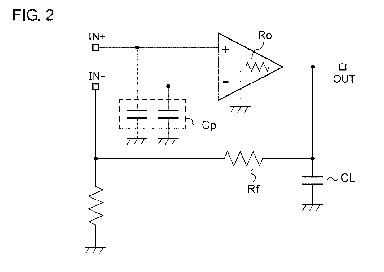
An RC filter is formed by a feedback resistor Rf and a parasitic capacitance Cp, thereby causing a phase delay.
An output resistance Ro of the amplifier and a load capacitance CL generated in the application also form the RC filter, thereby causing the phase delay.

Method used


Image

  • Operational amplifier
  • Operational amplifier
  • Operational amplifier

Examples


Embodiment Construction

[0028]The invention will now be described based on preferred embodiments which do not intend to limit the scope of the present invention but exemplify the invention. All of the features and the combinations thereof described in the embodiment are not necessarily essential to the invention.

[0029]In the present specification, “a state where a member A is connected to a member B” includes, in addition to a case where the member A and the member B are physically and directly connected, a case where the member A and the member B are indirectly connected via another member which does not affect an electrical connection state or does not hinder functions of the member A and the member B.

[0030]Similarly, “a state where a member C is provided between the members A and the member B” includes, in addition to a case where the member A and the member B or the member B and the member C are directly connected, a case where the member A and the member B or the member B and the member C are indirect...


PUM


Abstract

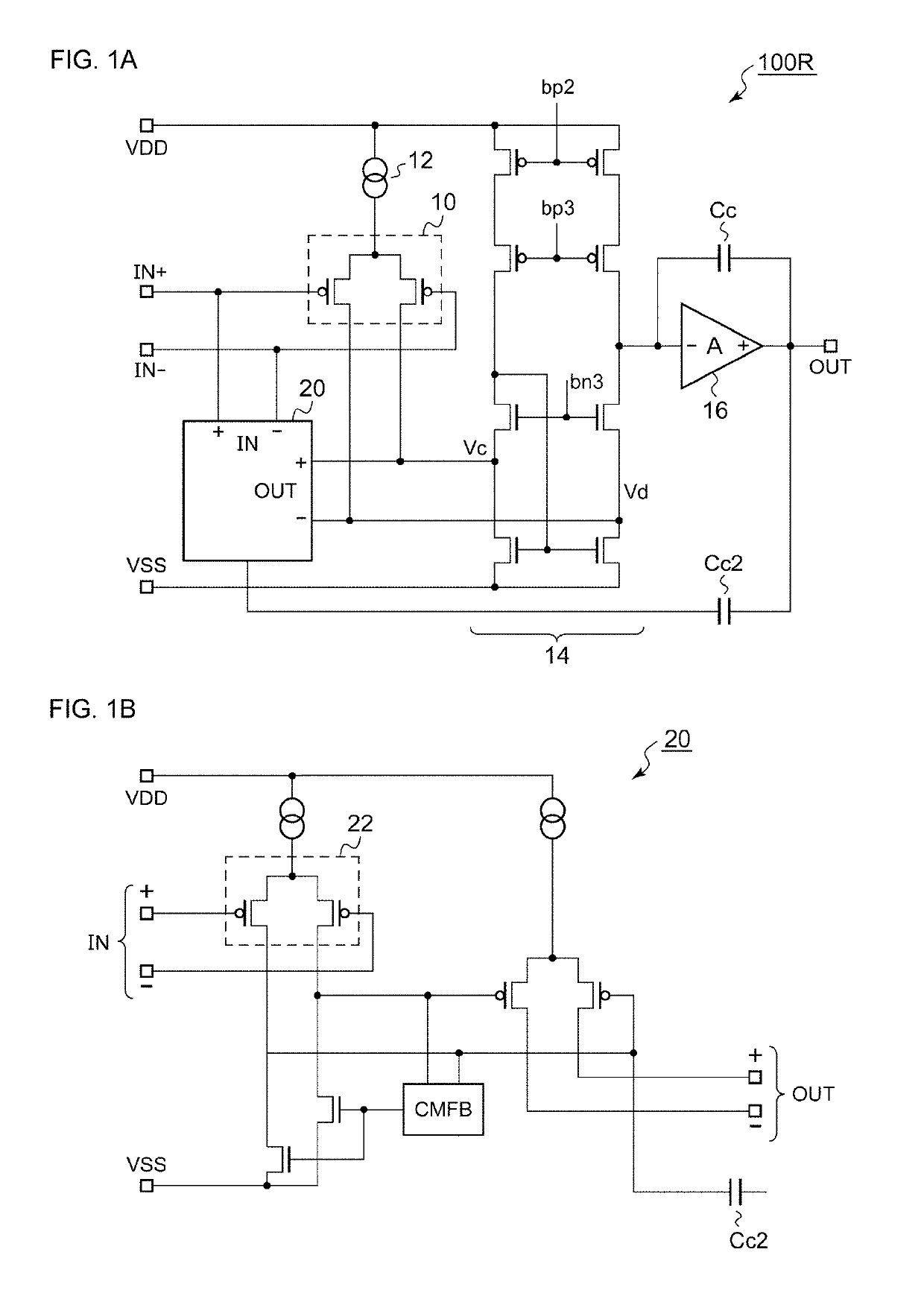
An operational amplifier includes a gain boost circuit. The gain boost circuit includes a first differential gm amplifier of a first stage, and a second differential gm amplifier of a post stage. Phase compensation capacitors are provided between inputs and outputs of a system of the second differential gm amplifier.

Description

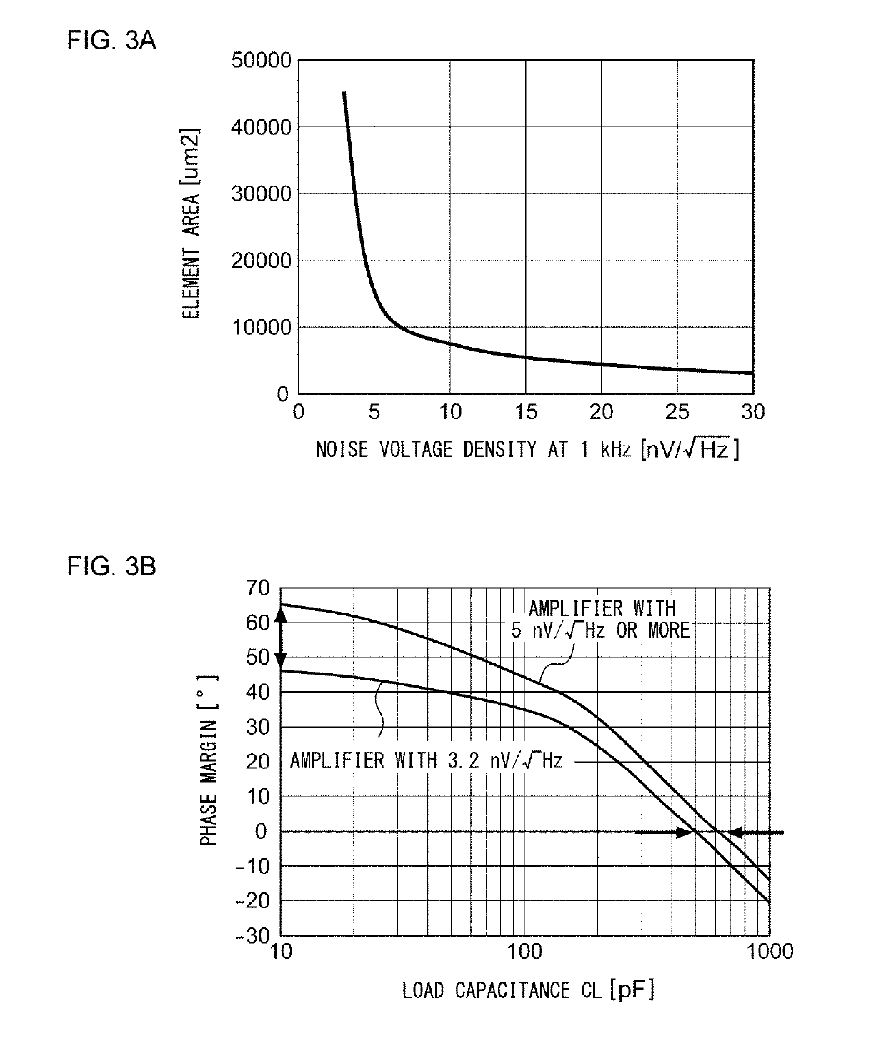
CROSS-REFERENCE TO RELATED APPLICATION[0001]The present application claims priority under 35 U.S.C. § 119 to Japanese Patent Application No. 2017-252125, filed on Dec. 27, 2017, the entire contents of which are incorporated herein by reference.BACKGROUND OF THE INVENTION1. Field of the Invention[0002]The present invention relates to an operational amplifier.2. Description of the Related Art[0003]In many electronic circuits, an operational amplifier (differential amplifier) is used. For amplification of a minute signal, reduction of noise of the operational amplifier is required. At present, as a complementary metal oxide semiconductor (CMOS) operational amplifier with low noise, one with an equivalent input noise voltage of 5.5 nv / √Hz at 1 kHz is commercially available (NJU77806 manufactured by New Japan Radio Co., Ltd.).[0004]FIG. 1A and FIG. 1B are circuit diagrams of a CMOS operational amplifier. A CMOS operational amplifier 100R in FIG. 1A includes a differential input pair 10, ...

Claims


Application Information

Patent Timeline
IPC IPC(8): H03F3/45H03F1/26H03G3/30
CPCH03F3/45273H03F3/45269H03F1/26H03G3/30H03F2203/45156H03F2203/45338H03F3/45192H03F3/45659H03F2203/45652
Inventor NOMURA, NAOHIROMANABE, TAKATOSHI
Owner ROHM CO LTD
Learn More