Bi-directional reversible submersible motor

a submersible motor and bi-directional technology, applied in the direction of positive displacement liquid engines, pumps, machines/engines, etc., can solve the problems of high noise and high consumption of submersible motors during operation, and achieve the effect of saving electric power supply consumption and not causing significant vibration or noise during operation

Inactive Publication Date: 2009-05-19
CHEN CHI DER
View PDF7 Cites 0 Cited by
  • Summary
  • Abstract
  • Description
  • Claims
  • Application Information

AI Technical Summary

Benefits of technology

[0005]The present invention has been accomplished under the circumstances in view. It is the main object of the present invention to provide a submersible motor, which is operable to selectively pump water between two reversed directions. It is another object of the present invention to provide a submersible motor, which saves consumption of electric power supply. It is still another object of the present invention to provide a submersible motor, which does not cause significant vibration or noise during operation.

Problems solved by technology

This design of submersible motor consumes much electric energy, and causes a high noise during operation.

Method used


Image

  • Bi-directional reversible submersible motor
  • Bi-directional reversible submersible motor
  • Bi-directional reversible submersible motor

Examples


first embodiment

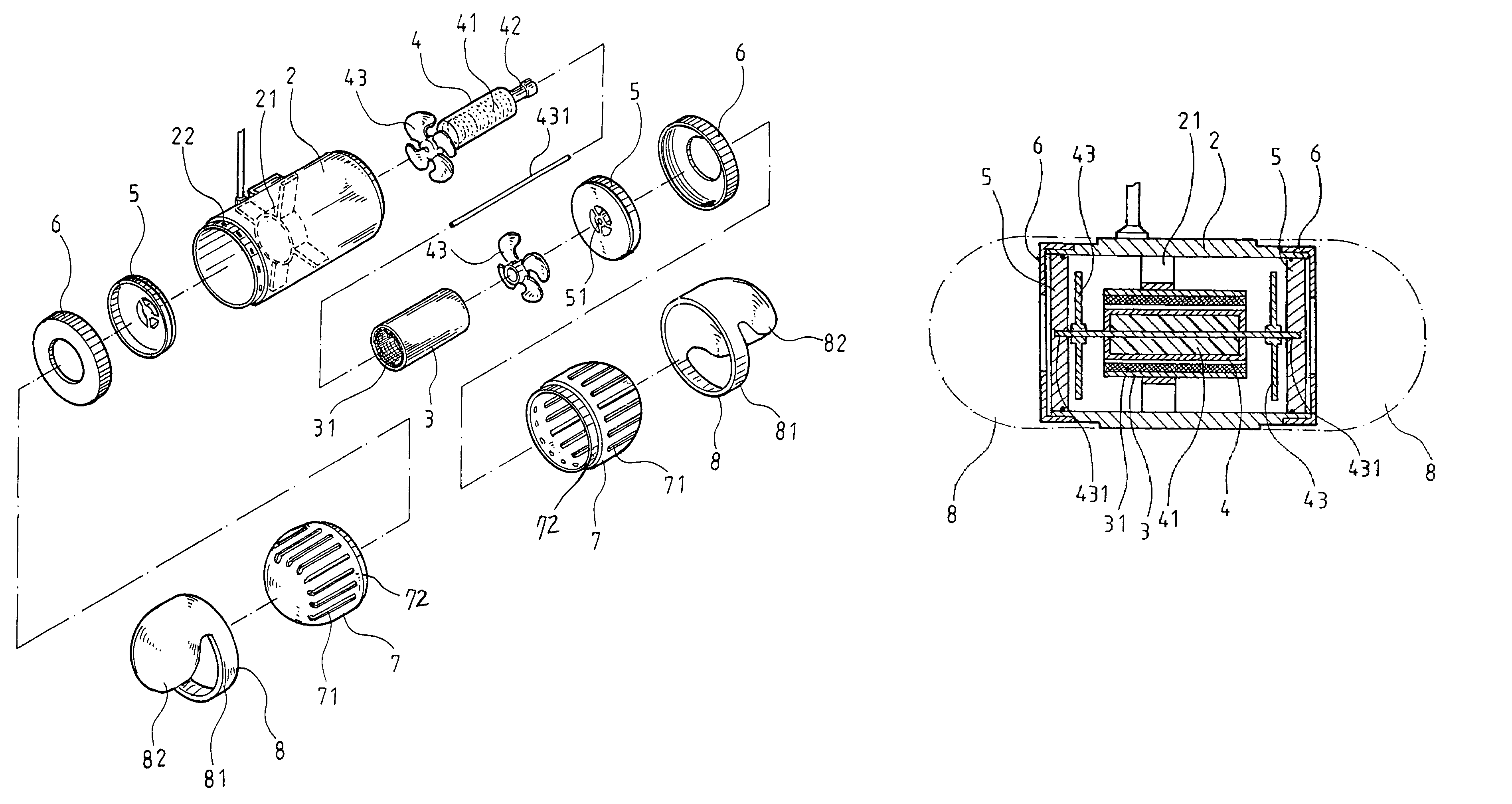
[0016]Referring to FIGS. 2˜4, a bi-directional reversible submersible motor in accordance with the present invention is shown comprising:

[0017]a housing 2, which has a bracket 21 on the inside of the hollow cylindrical body thereof and a plurality of mounting holes 22 around the periphery of the two opposite open ends thereof;

[0018]a sleeve 3, which is affixed to the bracket 21 inside the housing 2, having a winding 31 arranged around the inside wall thereof;

[0019]a shaft and fan blade assembly 4, which comprises a tubular shaft 42 inserted through the sleeve 3, a magnet 41 affixed to and extending around the periphery of the tubular shaft 42 and suspending in the sleeve 3, two fan blades 43 respectively fastened to the two distal ends of the tubular shaft 42, and a locating rod 431 inserted through the center of each of the fan blades 43 and the tubular shaft 42;

[0020]two water guide plates 5, which are respectively fastened to the two opposite open ends of the housing 2, each havi...

third embodiment

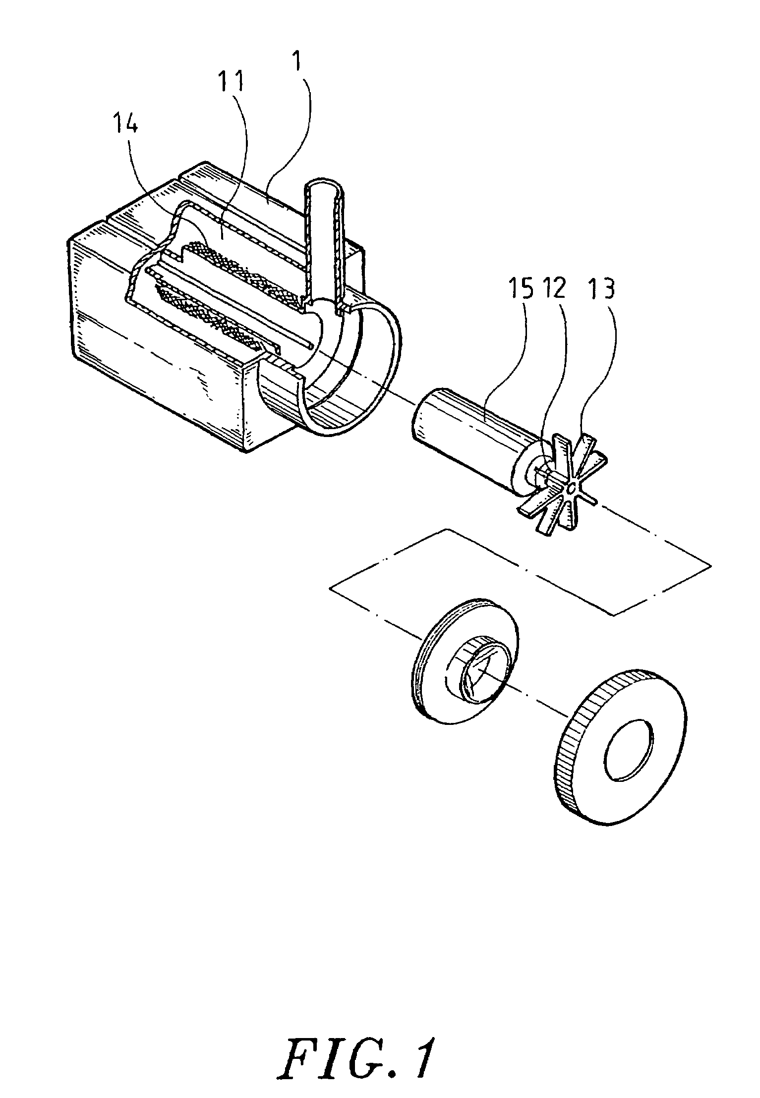
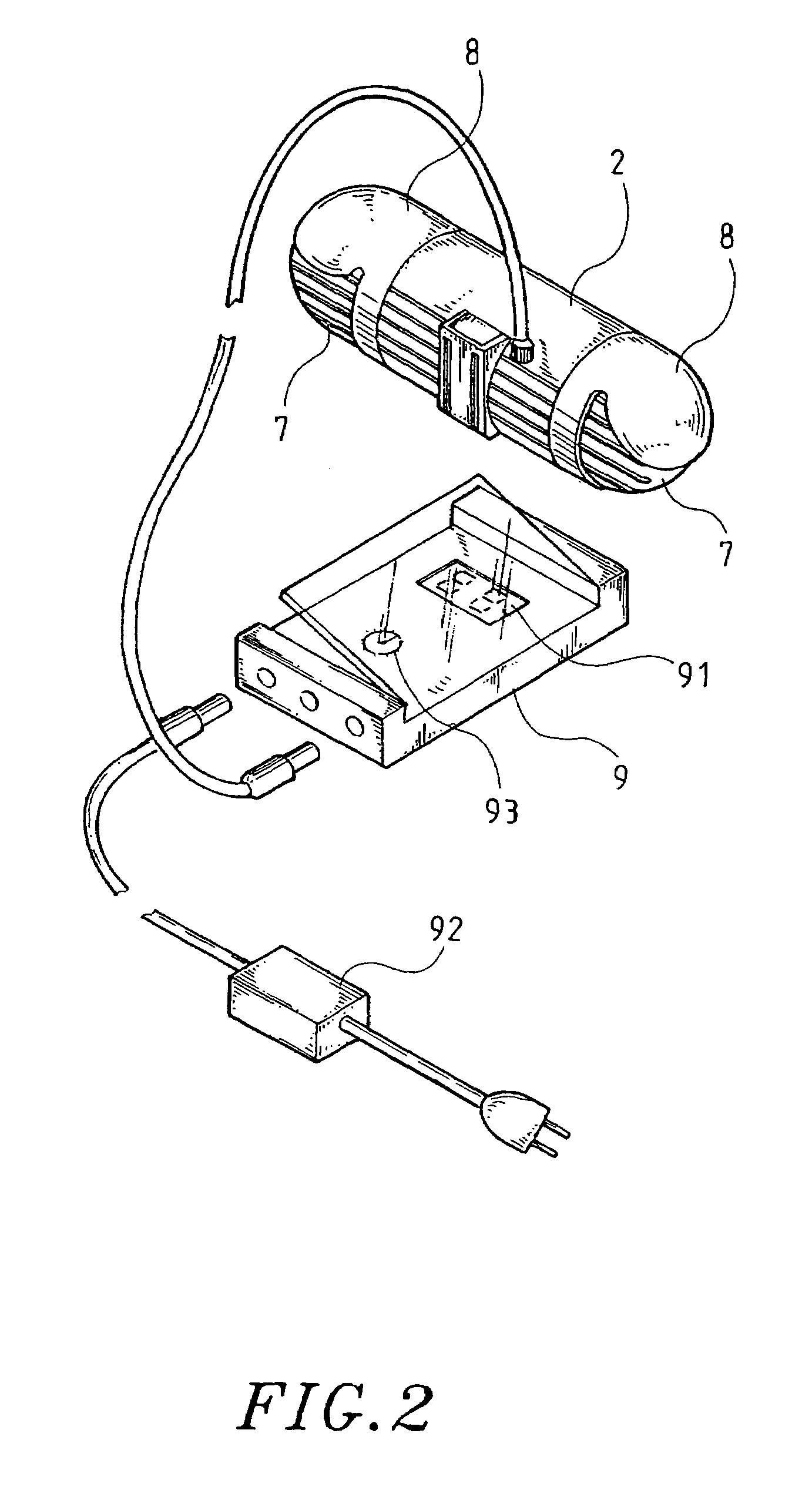
[0028]FIGS. 8 and 9 show a bi-directional reversible submersible motor in accordance with the present invention. According to this embodiment, the winding 31 is fixedly provided inside the cylindrical housing 101, and the magnetic shaft and fan blade assembly 4 is supported on a locating rod 431 inside the housing 101. The locating rod 431 is connected between two water guide plates 5 at the two distal open ends of the housing 101. Further, two caps 6 are respectively capped on the two distal open ends of the housing 101, and covered on the water guide plates 5. Further, the housing 101 has water inlets 102 on the periphery of each of the two distal open ends.


PUM


Abstract

A bi-directional reversible submersible motor, which includes a housing having an inside bracket, two water guide plates fastened to the two distal ends of the housing and covered with a respective cap, a locating rod connected between the water guide plates, a sleeve affixed to the bracket and holding a winding, a magnetic shaft and fan blade assembly rotatably supported on the locating rod in the sleeve for rotating two fan blades to pump water when the winding is electrically energized, and a controller for controlling the supply of electric current to the winding to control the direction and time of rotation of the fan blades.

Description

BACKGROUND OF THE INVENTION[0001]1. Field of the Invention[0002]The present invention relates to a submersible motor and more particularly, to a high-speed, high-capacity, bi-directional reversible submersible motor that is small-sized and does not cause significant vibration during operation.[0003]2. Description of the Related Art[0004]FIG. 1 shows a submersible motor for use in an aquarium. According to this design, the submersible motor comprises a housing 1. The housing 1 has a cylindrical chamber 11. A winding 14 is mounted inside the housing 1 around the chamber 11. A shaft 12 is inserted into the cylindrical chamber 11, having a vane wheel 13 provided at the front side thereof and suspending outside the housing 1 and a magnet 15 provided at the rear side thereof. When electric current is connected to the winding 14, the magnet 15 is induced to rotate, thereby causing the vane wheel to pump water. This design of submersible motor consumes much electric energy, and causes a hig...

Claims


Application Information

Patent Timeline
Patent Type & Authority Patents(United States)
IPC IPC(8): H02K5/12F04B17/00H02K47/00
CPCF04D3/00H02K5/132F04D13/086
Inventor CHEN, CHI-DER
Owner CHEN CHI DER
Why Eureka
Try Eureka