Reduced wind resistant haulage vehicle apparatus

a technology for hauling vehicles and wind resistance, applied in the field of hauling vehicles, can solve the problems of significant reduction of the air resistance of the vehicle, saving vehicle energy demand and fuel consumption, and reducing the noise and vibration of the motor, so as to reduce the noise and vibration of the motor and reduce the wind resistance. , the effect of reducing the noise and vibration

Inactive Publication Date: 2008-07-31
BREAKFIELD KENNETH R
View PDF27 Cites 25 Cited by
  • Summary
  • Abstract
  • Description
  • Claims
  • Application Information

AI Technical Summary

Benefits of technology

[0012]More specifically, the haulage portion includes haulage compartment side walls. Haulage compartment front doors are connected to the haulage compartment side walls. Haulage compartment rear doors are connected to the haulage compartment side walls. Preferably, the front doors open inward with respect to the haulage portion. Also, preferably, the rear doors open inward with respect to the haulage portion. When the haulage portion is empty, the front doors and the rear doors are opened, and air flow can flow through the haulage portion when the vehicle is driven along a road surface. As a result, the air resistance of the vehicle is significantly reduced, and the vehicle saves in energy demand and in fuel consumption.
[0025]Even another object of the present invention is to provide a new and improved reduced wind resistance haulage vehicle apparatus that permits some wheels and tires to be elevated above the road surface, so that they do not roll along the road surface when the haulage compartment is empty.

Problems solved by technology

As a result, the air resistance of the vehicle is significantly reduced, and the vehicle saves in energy demand and in fuel consumption.

Method used


Image

  • Reduced wind resistant haulage vehicle apparatus
  • Reduced wind resistant haulage vehicle apparatus
  • Reduced wind resistant haulage vehicle apparatus

Examples


Embodiment Construction

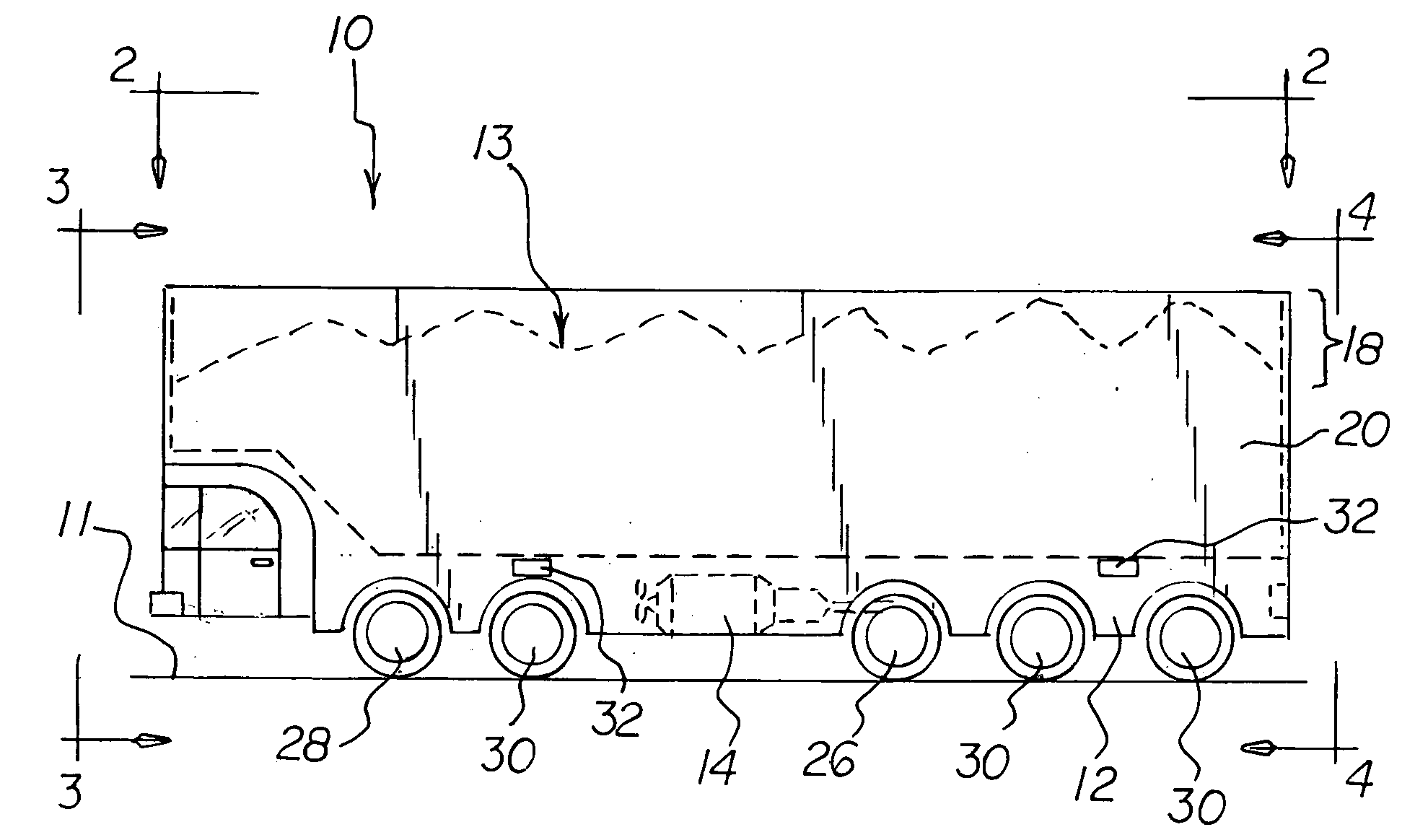
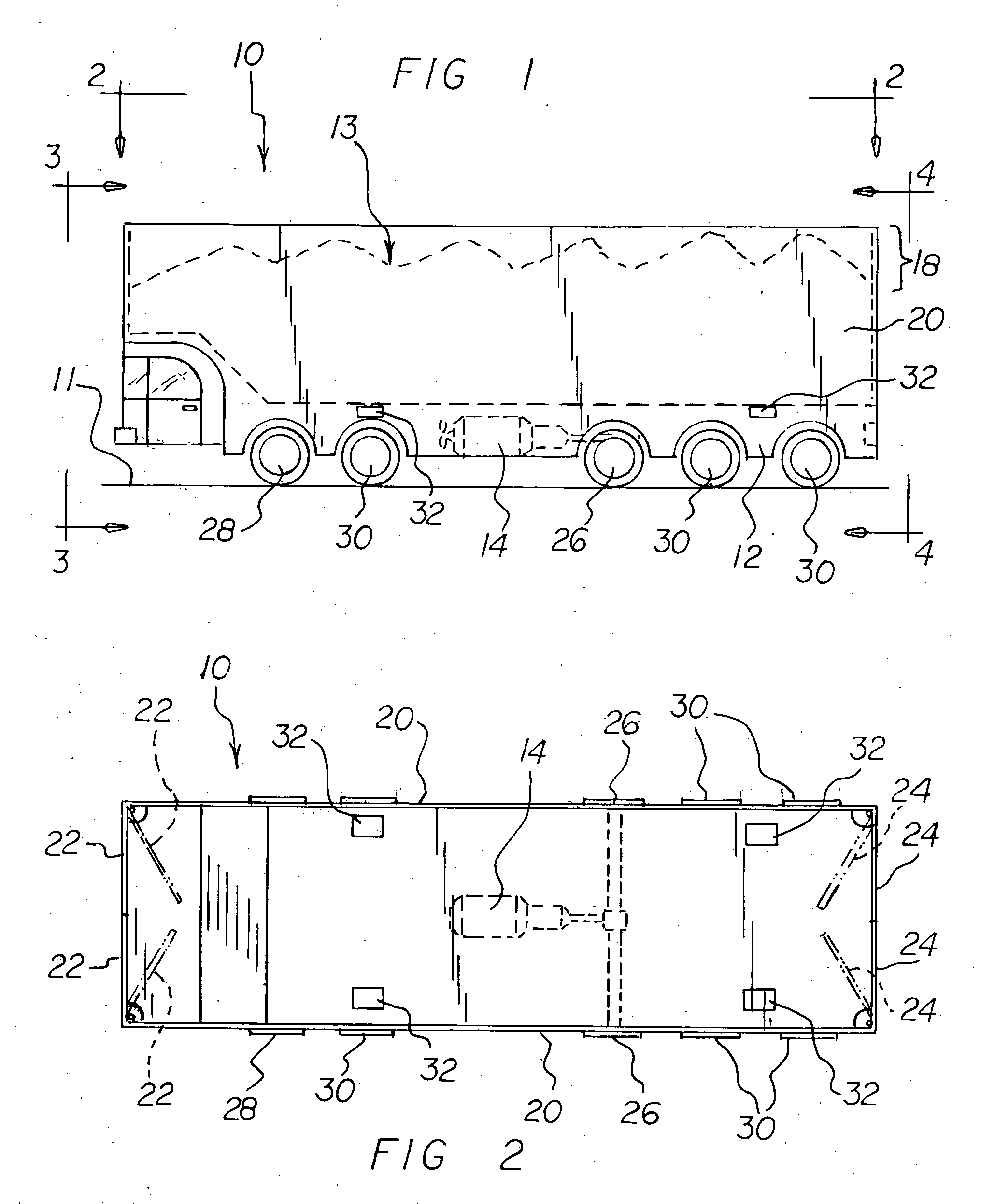
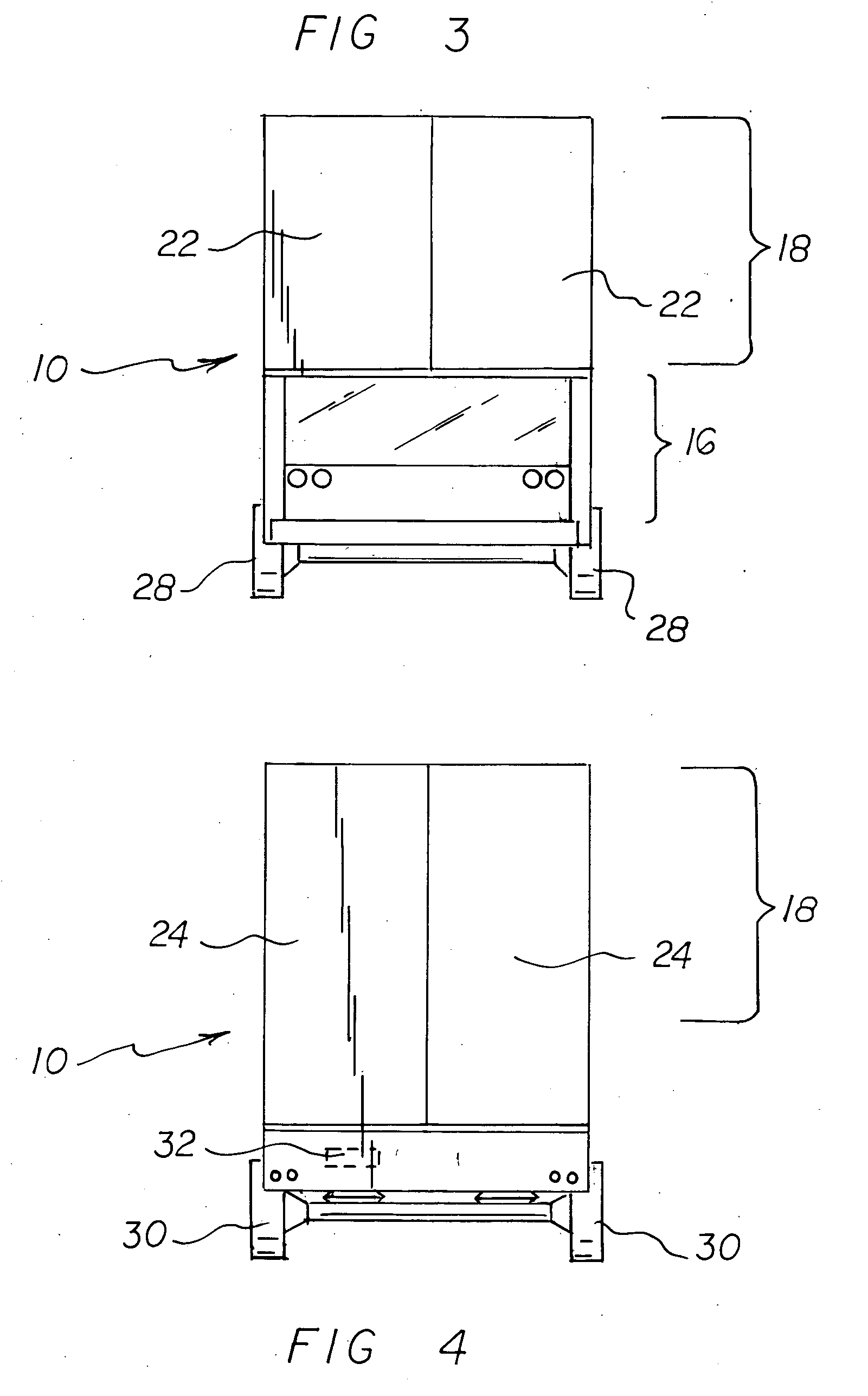
[0036]With reference to the drawings, a new and improved reduced wind resistance haulage vehicle apparatus embodying the principles and concepts of the present invention will be described.

[0037]Turning to FIGS. 1-8, there is shown a preferred embodiment of the reduced wind resistance haulage vehicle apparatus of the invention generally designated by reference numeral 10. In each of the figures, reference numerals are shown that correspond to like reference numerals that designate like elements shown in other figures.

[0038]In the preferred embodiment, a reduced wind resistance haulage vehicle apparatus 10 includes an undercarriage portion 12. The undercarriage portion 12 can be either framed or frameless (unibody). A motor / transmission 14 is supported by the undercarriage portion 12. Driven wheel assemblies 26 are connected to the undercarriage portion 12 and are powered by the motor / transmission 14. A cab portion 16 is supported by the undercarriage portion 12 at the front thereof s...


PUM


Abstract

A reduced wind resistance haulage vehicle apparatus includes an undercarriage portion which supports a motor / transmission. Driven wheel assemblies are connected to the undercarriage portion and are powered by the motor / transmission. A cab portion is supported by the an undercarriage portion for controlling the motor / transmission. Steering wheel assemblies are supported by the undercarriage portion for steering by a driver seated in the cab portion. A haulage portion is supported by the undercarriage portion. More specifically, the haulage portion includes haulage compartment side walls. Haulage compartment front doors and rear doors are connected to the haulage compartment side walls. When the haulage portion is empty, the front doors and the rear doors are opened, and air flow can flow through the haulage portion when the vehicle is driven along a road surface. As a result, the air resistance of the vehicle is significantly reduced, and the vehicle saves in energy demand and in fuel consumption.

Description

BACKGROUND OF THE INVENTION[0001]1. Field of the Invention[0002]The present invention relates generally to haulage vehicles, and, more particularly, to haulage vehicles especially adapted for reducing air resistance when an empty vehicle is driven.[0003]2. Description of the Prior Art[0004]It is well known in the art that when a vehicle is driven, air resistance is an important factor in causing excess fuel to be consumed, even if the haulage vehicle is empty. To reduce this effect, throughout the years, a number of innovations have been developed relating to the reduction of air resistance in haulage vehicles, and the following U. S. patents are representative of some of those innovations: U.S. Pat. Nos. 926,971, 5,782,521, and 6,685,256.[0005]More specifically, U. S. Pat. No. 926,971 discloses a railroad car that include front air intake tubes, a front to rear air conveyor duct, and rear air output tubes. Passage of air through the front air intake tubes, the front to rear air con...

Claims


Application Information

Patent Timeline
Patent Type & Authority Applications(United States)
IPC IPC(8): B60P7/02B62D61/12
CPCB62D35/001
Inventor BREAKFIELD, KENNETH R.
Owner BREAKFIELD KENNETH R
Why Eureka
Try Eureka