Hydraulic control apparatus of vehicle and control method

a technology of hydraulic control apparatus and control method, which is applied in the direction of piston pump, gearing, fluid coupling, etc., can solve the problems of not being able to necessarily and sufficiently secure a hydraulic pressure and working fluid, and achieve the effects of saving electric power consumption, and reducing the cost of the system

Inactive Publication Date: 2005-04-19
TOYOTA JIDOSHA KK
View PDF18 Cites 26 Cited by
  • Summary
  • Abstract
  • Description
  • Claims
  • Application Information

AI Technical Summary

Benefits of technology

[0011]In accordance with this structure, since it is possible to drive the first hydraulic pump for the power steering and the second hydraulic pump for the shift transmission control by one motor, the number of the parts is reduced in comparison with the case of using the independent driving motors, so that it is possible to intend to lighten the system as a whole, reduce the cost thereof and save the electric power consumption.
[0012]Further, since the motor is driven and controlled so as to have the higher rotational speed between the rotational speed of the first hydraulic pump for obtaining the amount of working fluid required in the power steering apparatus and the rotational speed of the second hydraulic pump for obtaining the amount of working fluid required for the shift transmission control of the automatic transmission, it is possible to necessarily and sufficiently secure the working fluids respectively required in the power steering apparatus and the shift transmission control which correspond to the hydraulic control circuits being independent from each other.

Problems solved by technology

However, in Japanese Unexamined Patent Publication No. 2000-27992 mentioned above, the control technique in the case of rotating a first hydraulic pump pressure feeding a working fluid required for a power steering apparatus, and a second hydraulic pump pressure feeding a working fluid required for a hydraulic control circuit executing a shift transmission control of the automatic transmission by a common electric motor is not disclosed.
Further, it is not possible to necessarily and sufficiently secure a hydraulic pressure of the working fluid required for the power steering apparatus and an amount of the working fluid required for the hydraulic control circuit executing the shift transmission control of the automatic transmission on the basis of a little electric power consumption.

Method used


Image

  • Hydraulic control apparatus of vehicle and control method
  • Hydraulic control apparatus of vehicle and control method
  • Hydraulic control apparatus of vehicle and control method

Examples


Embodiment Construction

[0030]A description will be in detail given below of an embodiment corresponding to one aspect of the present invention with reference to the accompanying drawings.

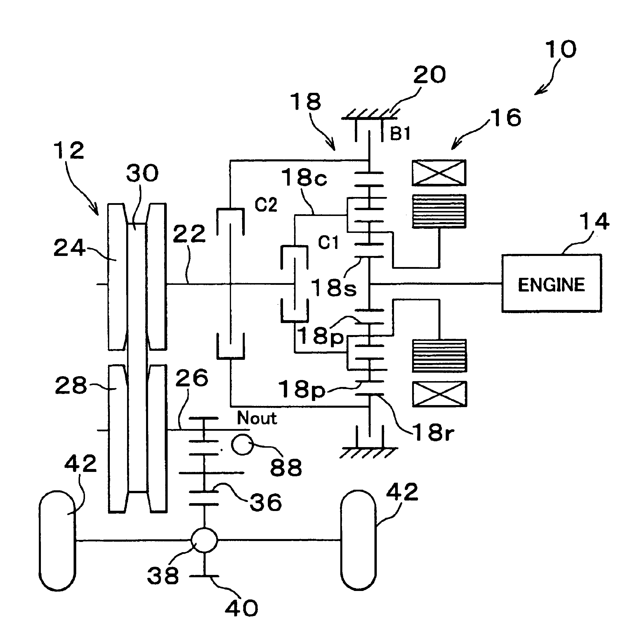
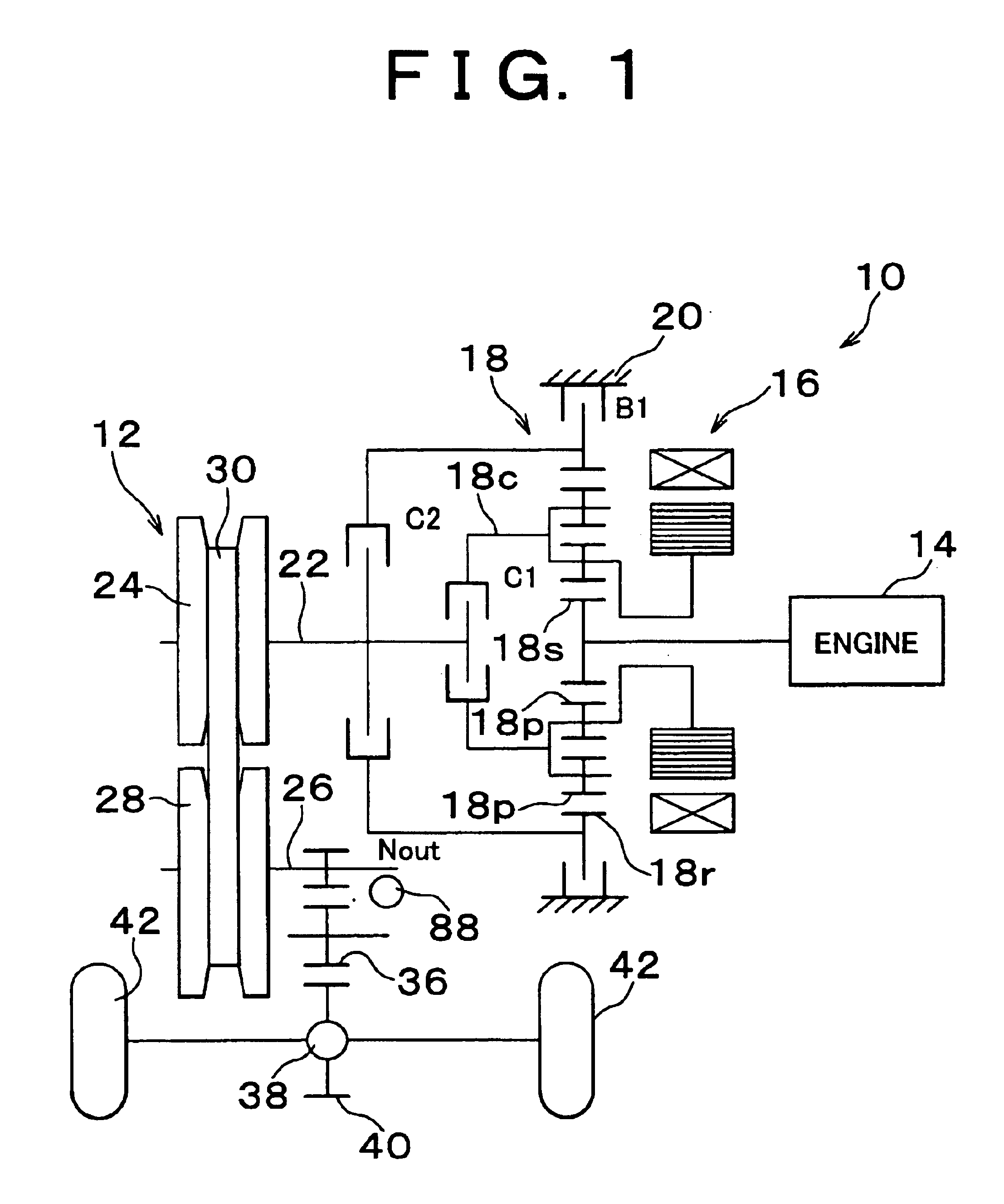
[0031]FIG. 1 is a skeleton view schematically showing a structure of a drive apparatus for a vehicle provided with a hydraulic control apparatus of an automatic transmission in accordance with one embodiment of the present invention, that is, a power transmission apparatus 10. The power transmission apparatus 10 corresponds to a power transmission apparatus for a so-called hybrid vehicle. The power transmission apparatus 10 is constituted by an engine 14 such as an internal combustion engine or the like generating a power on the basis of a combustion of a fuel, a motor generator 16 used as an electric motor and a power generator, a double pinion type planetary gear apparatus 18 and an automatic transmission 12. The power transmission apparatus 10 is horizontally mounted on a front engine front drive (FF) vehicle or the li...


PUM


Abstract

A first hydraulic pump and a second hydraulic pump are respectively mounted to both ends of a rotary shaft in an electric motor, whereby it is possible to drive both of the first hydraulic pump and the second hydraulic pump by one electric motor. Since the electric motor is driven and controlled so as to have any higher rotational speed among a rotational speed of the first hydraulic pump for obtaining an amount of working fluid required in a hydraulic control circuit for a power steering apparatus and a rotational speed of the second hydraulic pump for obtaining an amount of working fluid required in a hydraulic control circuit for a power train by a hydraulic pump drive controlling portion, it is possible to necessarily and sufficiently secure the working fluids respectively required in the power steering hydraulic control circuit and the power train hydraulic control circuit which are independent from each other, by a little electric power consumption.

Description

INCORPORATION BY REFERENCE[0001]The disclosure of Japanese Patent Application No. 2001-030890 filed on Feb. 7, 2001 and No. 2001-149358 filed on May 18, 2001, including the specification, drawings and abstract is incorporated herein by reference in its entirety.BACKGROUND OF THE INVENTION[0002]1. Field of the Invention[0003]The present invention relates to a hydraulic control apparatus of an automatic transmission for a vehicle, and more particularly to a control technique of a motor driving type hydraulic pump constituting a hydraulic power source.[0004]2. Description of the Related Art[0005]As a related art, there has been known an automatic transmission for a vehicle provided with respective hydraulic actuators for switching a shift transmission, driving a lock-up mechanism, circulating to an oil cooler and the like. Further, the automatic transmission for the vehicle is provided with a hydraulic control apparatus for controlling the hydraulic actuators. There is a case that a so...

Claims


Application Information

Patent Timeline
Patent Type & Authority Patents(United States)
IPC IPC(8): B60K6/04B60K6/00B62D5/06B62D5/065F16H61/00F16H61/662F16H61/66B60K6/48B60K6/543B60W10/30F16H3/72
CPCB60K6/48B60K6/543B60W10/30B62D5/065F16H61/0025F16H61/0031F16H61/66272B60L2260/14Y10S903/918F16H2200/2005Y02T10/6221F16H3/724B60W2050/0011Y02T10/62
Inventor ENDO, HIROATSUOZEKI, TATSUYAKASAMATSU, AKIRANAGASHIMA, NOBUYUKIUMEYAMA, MITSUHIRONOMOTO, HISANORIIWASE, YUJIMURAKAMI, AKIRANADA, MITSUHIRO
Owner TOYOTA JIDOSHA KK
Why Eureka
Try Eureka