Sealing valve arrangement for a shaft furnace charging installation

a technology for sealing valves and furnaces, which is applied in the direction of furnaces, charge manipulation, lighting and heating apparatus, etc., can solve the problems that the pressure difference between shaft furnaces and hoppers cannot be avoided, and the shutter movement can be increased, so as to reduce safety risks and maintenance costs, save electric power consumption, and generally more readily available electric power

Active Publication Date: 2019-09-12
PAUL WURTH SA
View PDF0 Cites 0 Cited by
  • Summary
  • Abstract
  • Description
  • Claims
  • Application Information

AI Technical Summary

Benefits of technology

[0012]However, this is precisely what the present invention suggests. Indeed, the shutter-actuating device of the present invention comprises an electric motor with a braking device associated therewith for stopping the output shaft of the electric motor from rotating once the shutter is in its sealing position. Once the braking device is engaged, the electric motor can be turned off, thus saving on electric power consumption. Furthermore, as the electric motor is turned off, there is no risk of it overheating and being thereby damaged.
[0013]The use of electric power instead of hydraulic power has the advantage that electric power is generally more readily available. There is no need to provide neither an expensive hydraulic power station, nor hydraulic piping. Also, safety risks and maintenance costs are reduced.
[0014]The additional movement of the shutter due to the pressure difference between shaft furnace and hopper is, according to the present invention, absorbed by the transmission means arranged between the output shaft of the electric motor and the tilting shaft. The transmission means has a backlash which is sufficient for allowing the tilting shaft to be rotated by a predetermined amount, without this rotation being transmitted to the output shaft of the electric motor. Thus, the electric motor and the braking device cannot be damaged by the extra movement of the shutter caused by the pressure difference between the shaft furnace and the hopper.

Problems solved by technology

The additional movement of the shutter due to the pressure difference between shaft furnace and hopper can hardly be avoided.

Method used


Image

  • Sealing valve arrangement for a shaft furnace charging installation
  • Sealing valve arrangement for a shaft furnace charging installation

Examples


Embodiment Construction

[0025]Generally, a shaft furnace installation comprises a shaft furnace with a shaft furnace charging installation arranged thereabove for feeding charge material into the shaft furnace.

[0026]The shaft furnace charging installation may comprise a single hopper. Generally however, two or more hoppers are provided, allowing one hopper to be filled with charge material, while the charge material of another hopper is fed into the shaft furnace. As is well known in the art, each hopper comprises a material gate at the hopper outlet for maintaining the charge material in the hopper or releasing the charge material into the shaft furnace. Each hopper is furthermore equipped with an upper seal valve at the hopper inlet and a lower seal valve at the hopper outlet. These upper and lower seal valves are used to seal off the hopper pressure from atmosphere and from furnace pressure, respectively.

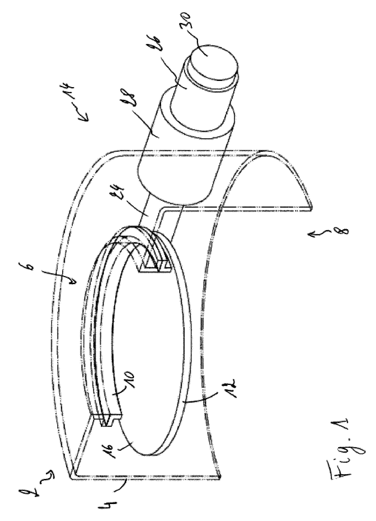
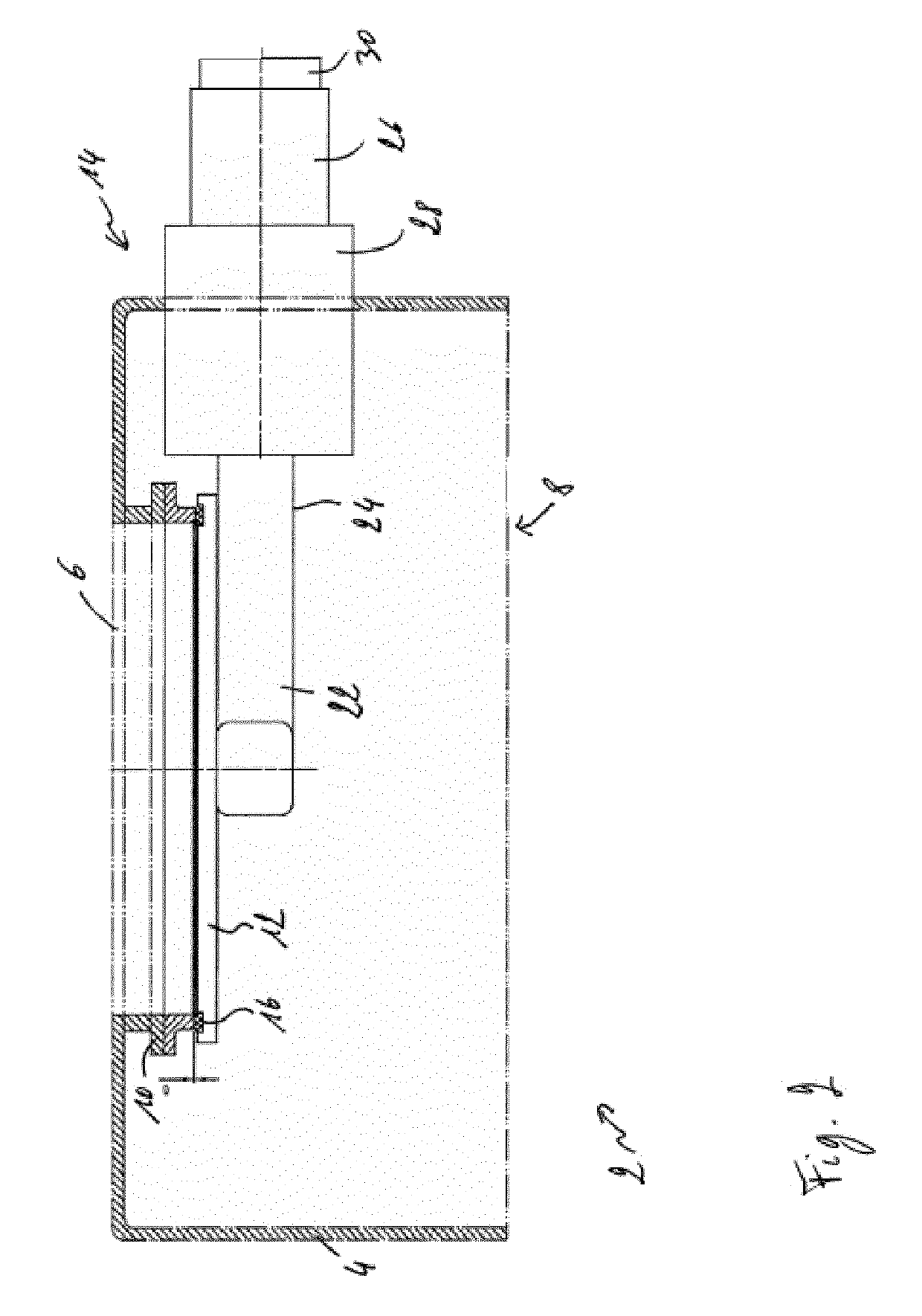
[0027]FIGS. 1 and 2 schematically represent a lower seal valve assembly 2 of a shaft furnace chargin...


PUM


Abstract

A sealing valve arrangement for a shaft furnace charging installation including a shutter that cooperates with a valve seat and a shutter-actuating device for moving the shutter between a closed position in sealing contact with the valve seat and an open position remote from the valve seat, where the shutter-actuating device includes a tilting shaft connected to the shutter, an electric motor with an output shaft connected to the tilting shaft, and a braking device associated with the electric motor, where the braking device is configured for, when engaged, preventing the output shaft of the electric motor from rotating, the shutter-actuating device further including a transmission means arranged between the output shaft of the electric motor and the tilting shaft, wherein the transmission means is configured for transmitting rotational movement of the output shaft of the electric motor to the tilting shaft, where the transmission means includes a backlash configured for having a predetermined amount of allowed rotation between the output shaft of the electric motor and the tilting shaft.

Description

TECHNICAL FIELD[0001]The present invention generally relates to a sealing valve arrangement for a shaft furnace charging installation and more specifically to an upper or lower sealing valve arrangement for preventing furnace gas loss in a blast furnace charging installation.BACKGROUND ART[0002]Shaft furnace charging installations of the BELL LESS TOP® type have found widespread use in industry over the last decades. An early example of such an installation is disclosed e.g. in U.S. Pat. No. 4,071,166. This installation minimizes escape of blast furnace gas from the furnace throat by operating one or more intermediate charge material storage hoppers in the manner of a sluice or airlock. To this effect, each hopper has an upper sealing valve and a lower sealing valve for sealing closure of the hopper inlet and outlet respectively. During filling of the hopper, the upper sealing valve is open whilst the lower sealing valve is closed. When material is charged from the hopper into the f...

Claims


Application Information

Patent Timeline
Patent Type & Authority Applications(United States)
IPC IPC(8): F27B1/20F16K1/20
CPCF27D2003/105F27B1/20F16K1/2007F16K31/043F27D3/10C21B7/18C21B7/20
Inventor STEICHEN, CHARLESHUTMACHER, PATRICKTOCKERT, PAUL
Owner PAUL WURTH SA
Why Eureka
Try Eureka