Roller shutter

a roller shutter and roller technology, applied in the direction of shutters/movable grilles, door/window protective devices, construction, etc., can solve the problems of increased exchanging cost and long repairing time, shutters may closed, and shutters also might become impossible to be opened or closed, etc., to achieve good overall flexibility, reduce the effect of pulling force and greatly reduce the wound diameter

Active Publication Date: 2015-05-28
LEE RAE YOUNG
View PDF8 Cites 6 Cited by
  • Summary
  • Abstract
  • Description
  • Claims
  • Application Information

AI Technical Summary

Benefits of technology

[0039]The present invention has advantages wherein the flexibility as a whole is good thanks to the structure wherein a plurality of slats are pivotally interconnected. When such slats are wound on a winding unit, the wound diameter may be greatly reduced, so the entire length of the shutter may be increased, and each slat includes a hollow part, so that the slats become lighter, and the pulling force may be greatly reduced, thus saving the consumption of electric power.
[0040]The present invention has advantages wherein the inner surface of the hook part and the first inner surface of the accommodation groove part have same radiuses, and the outer surface of the hook part and the second inner surface of the accommodation groove part have same radiuses, so the hook part of the slat of one side provides a smooth pivoting operation while maintaining an airtight sealing inside of the accommodation groove part of the slat of the other side. In addition, the pivoting operation may be performed in a smooth sliding manner without using any lubricant, which results in a silent opening or closing operation without generating any noises.
[0041]In the present invention, a buffer material is disposed at each portion where the hook part and the accommodation groove part come into contact with each other, so that it is possible to buffer the impacts when the hook part and the accommodation groove part contact with each other while the interconnected slats pivot.
[0042]In addition, the present invention has advantages wherein the cylindrical part of the slat has a non-uniform thickness in a circumferential direction, so it is possible to obtain an increased resisting force against any impacts when the end of the hook part comes into contact with the closed surface of the accommodation groove part while the interconnected slats pivot, while preventing any noises which might occur due to the impacts.

Problems solved by technology

In case that a wind speed is over 45 m / s, the slat may be deformed by wind force, so the slat might be derailed from a guide rail, so the shutter might become impossible to be opened and closed.
Except for the above problem, when the shutter is deformed by means of an external impact, the shutter also might become impossible to be opened or closed.
Meanwhile, in case of the related roller shutter, when the slat is deformed by wind pressure or external impact, it needs to exchange the whole structure of a door unit of the shutter, which results in the increased exchanging cost and long repairing time.
Since the conventional roller shutter is formed in a complicated structure wherein many components are used, the manufacturing cost increases, and the productivity decreases.

Method used


Image

  • Roller shutter
  • Roller shutter
  • Roller shutter

Examples


Embodiment Construction

[0054]The exemplary embodiment of the present invention will be described with reference to the accompanying drawings. For reference, the dimensions of the components and the thicknesses of the lines in the drawings might be exaggerated for the sake of easier understanding. The terms used throughout the descriptions of the present invention are defined in consideration of the functions of the present invention, so they may differ in accordance with the user, the operator's intention, practice, etc. Therefore, any definitions on such terms should be interpreted based on the contents throughout the present specification.

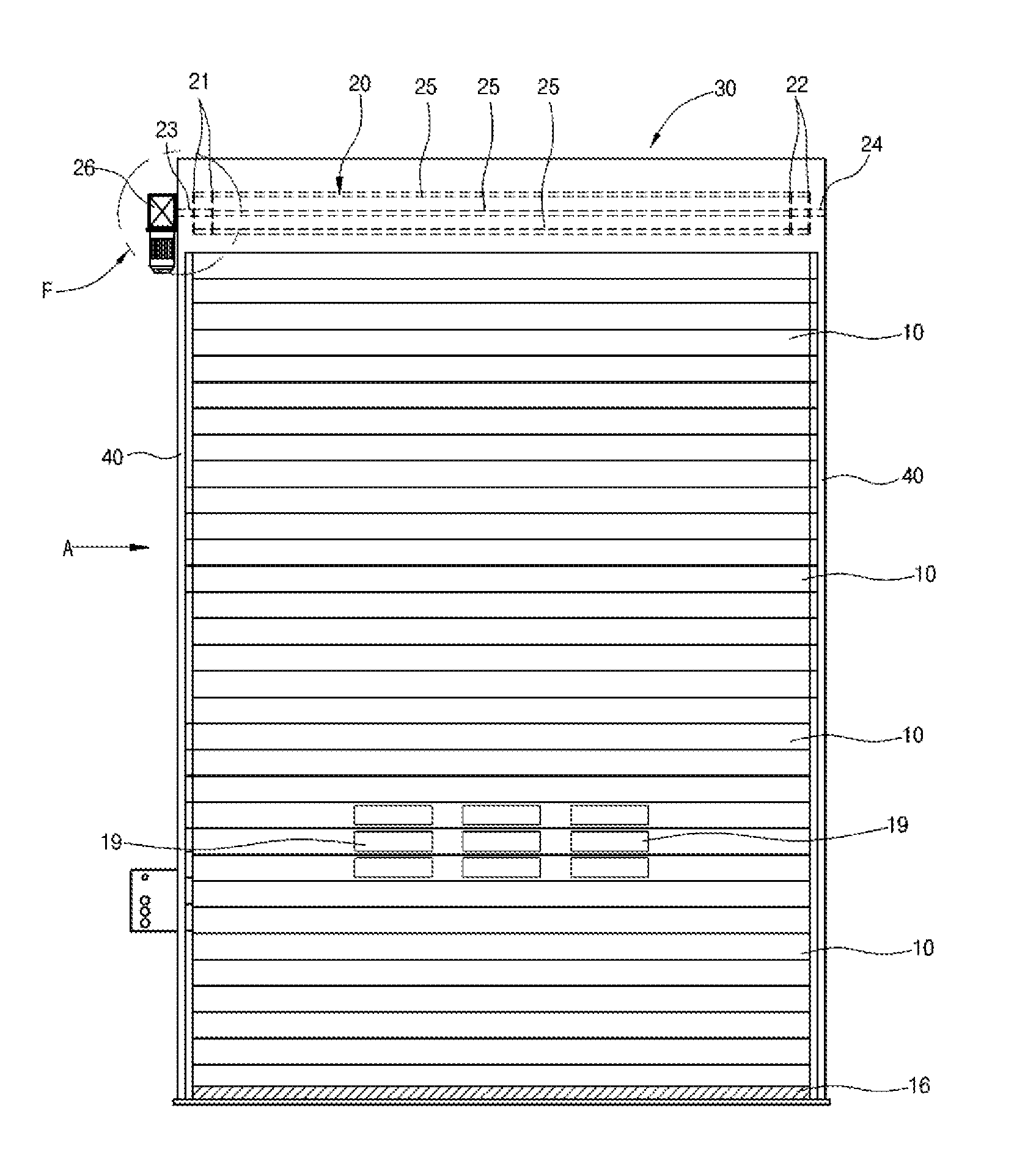
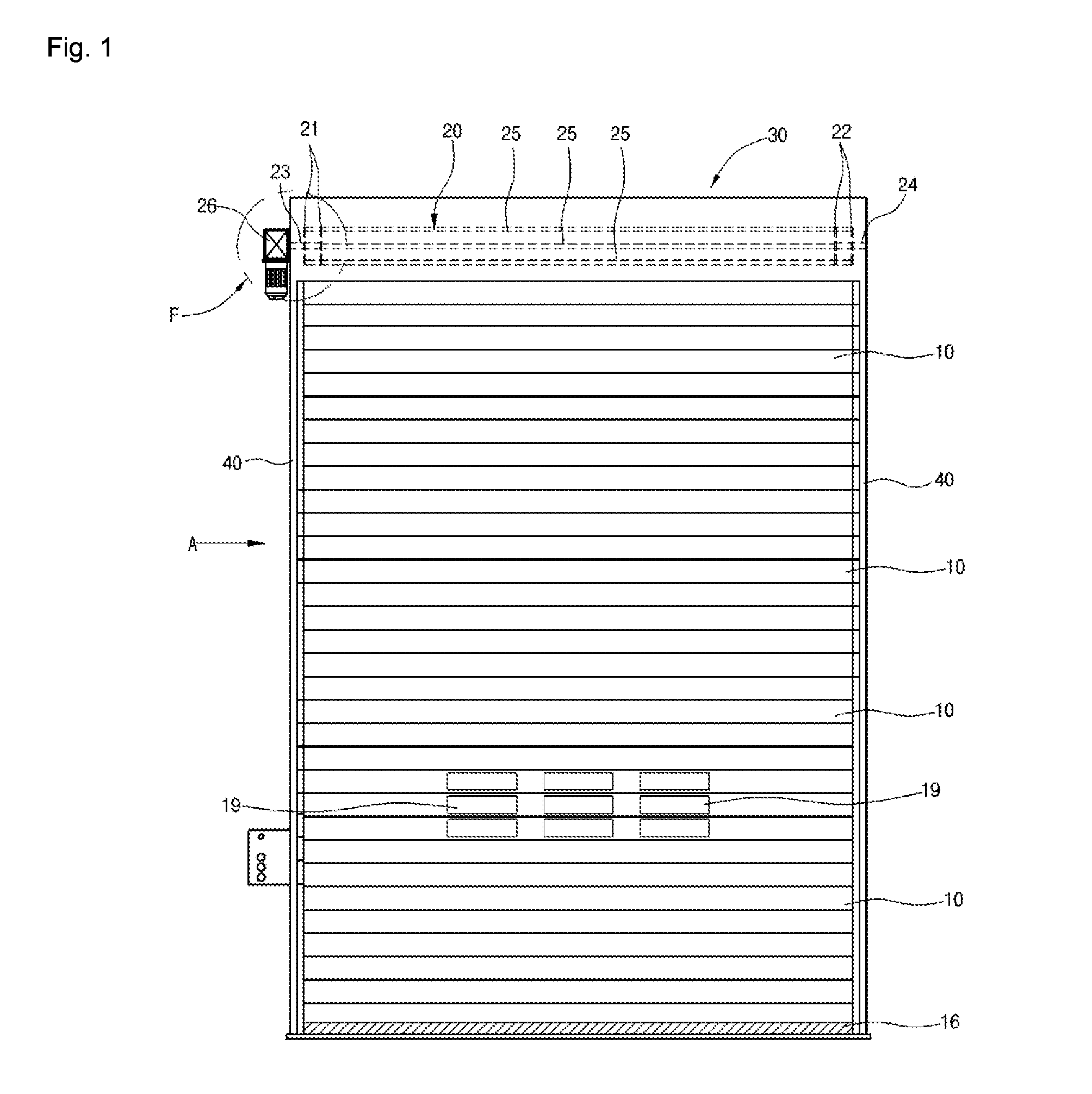
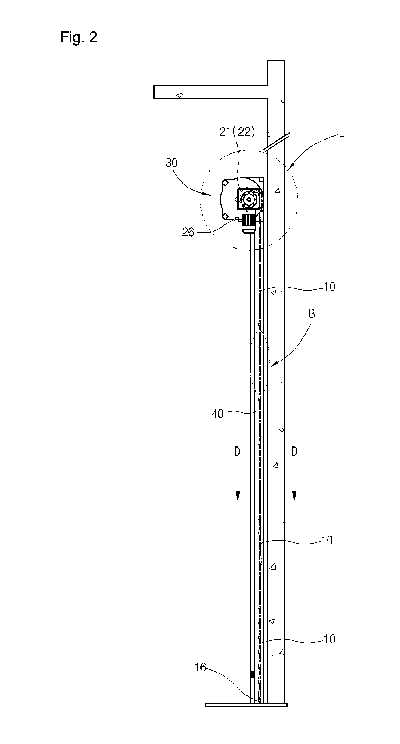
[0055]FIGS. 1 to 10 are views illustrating a roller shutter according to the present invention.

[0056]As illustrated therein, the roller shutter according to the present invention includes a plurality of slats 10 which are continuously connected in upward and downward directions, a winding unit 20 which is configured to wind or unwind the plurality of the slats 10 in th...


PUM


Abstract

The present invention relates to a roller shutter in which a slat connection structure is very flexible so as to reduce manufacturing and maintenance costs. The roller shutter of the present invention comprises: a plurality of slats continuously connected in the vertical direction; a winding unit for winding or unwinding the plurality of slats in the vertical direction; a shutter box arranged above a door frame of a building; and a guide frame for guiding the edges of the plurality of slats. The winding unit is arranged inside the shutter box. The plurality of slats are connected in the vertical direction such that the slats can be pivoted. One end of each slat has a hook, and the hook is curved with a predetermined radius of curvature. The other end of each slat has an accommodation groove curved at a predetermined radius of curvature. The hook of one slat is accommodated in the accommodation groove of another slat adjacent to said slat such that the hook is movable in the circumferential direction, thus enabling said slat and the other slat adjacent thereto in the vertical direction to pivot relative to one another. The hook has an inner surface and an outer surface. The accommodation groove has a first inner surface, a second inner surface, a closed surface, and an opening. The radius of the second inner surface of the accommodation groove is larger than that of the first inner surface. The first inner surface extends in the circumferential direction so as to form a cylinder. The inner surface of the hook and the first inner surface of the accommodation groove have the same radius, and the outer surface of the hook and the second inner surface of the accommodation groove have the same radius.

Description

TECHNICAL FIELD[0001]The present invention relates to a roller shutter, and in particular to a roller shutter which is capable of reducing a manufacturing cost and a maintenance cost since a structure for connecting slats is very flexible.BACKGROUND ART[0002]In general, a roller shutter is designed to open or close a shutter in such a manner that a plurality of slats made from a narrow and longitudinal steel sheet or aluminum are continuously interconnected and wound on or unwound from a rotary shaft installed inside of a shutter box at the top of a door frame.[0003]In a place such as a beach or a plain, a building wherein a shutter is installed might receive strong wind. At this time, the wind pressure resistance criteria of a typical slat is below 45 m / s. In case that a wind speed is over 45 m / s, the slat may be deformed by wind force, so the slat might be derailed from a guide rail, so the shutter might become impossible to be opened and closed.[0004]Except for the above problem,...

Claims


Application Information

Patent Timeline
Patent Type & Authority Applications(United States)
IPC IPC(8): E06B9/42
CPCE06B9/42E06B9/15E06B9/171E06B9/581E06B9/70E06B2009/1544E06B2009/1527
Inventor LEE, RAE YOUNG
Owner LEE RAE YOUNG
Why Eureka
Try Eureka