Solid state image pickup device

Inactive Publication Date: 2005-05-24
CANON KK
View PDF18 Cites 2 Cited by
  • Summary
  • Abstract
  • Description
  • Claims
  • Application Information

AI Technical Summary

Benefits of technology

[0010]The object of the present invention is to provide a solid state image pickup device, capable of saving the electric power consumption.

Problems solved by technology

However such conventional operation of the image sensor chip solely by the external drive causes a drawback in certain situations.
For example, such drawback occurs in a case where the image sensor chip performs a preliminary operation and a main operation, in which the main operation accesses the required image information, and the preliminary operation monitors the projection of the required image onto the image sensor chip.

Method used


Image

  • Solid state image pickup device
  • Solid state image pickup device
  • Solid state image pickup device

Examples


second embodiment

[0030]In the second embodiment shown in FIG. 4, in the preliminary operation, the image sensor chip 1 operates at the timing of the reference clock generation circuit 7 formed in the drive pulse generation chip 4, and the microcomputer 2 remains in the turned-off state.

first embodiment

[0031]As in the first embodiment, the control is switched to the microcomputer 2 when it is turned on, thereby suppressing the power consumption of the microcomputer 2 in the preliminary operation and also suppressing the power consumption in the entire device.

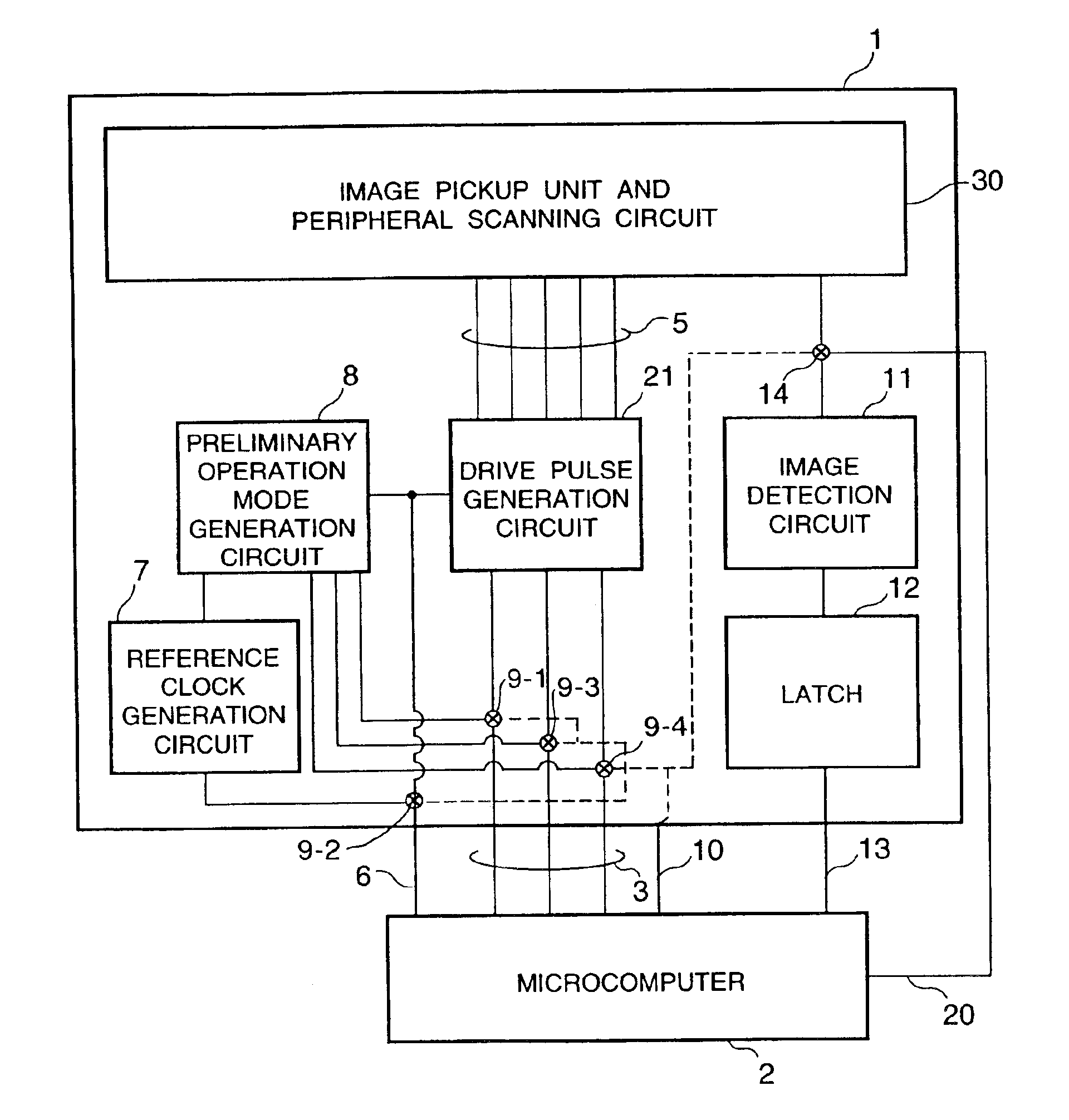
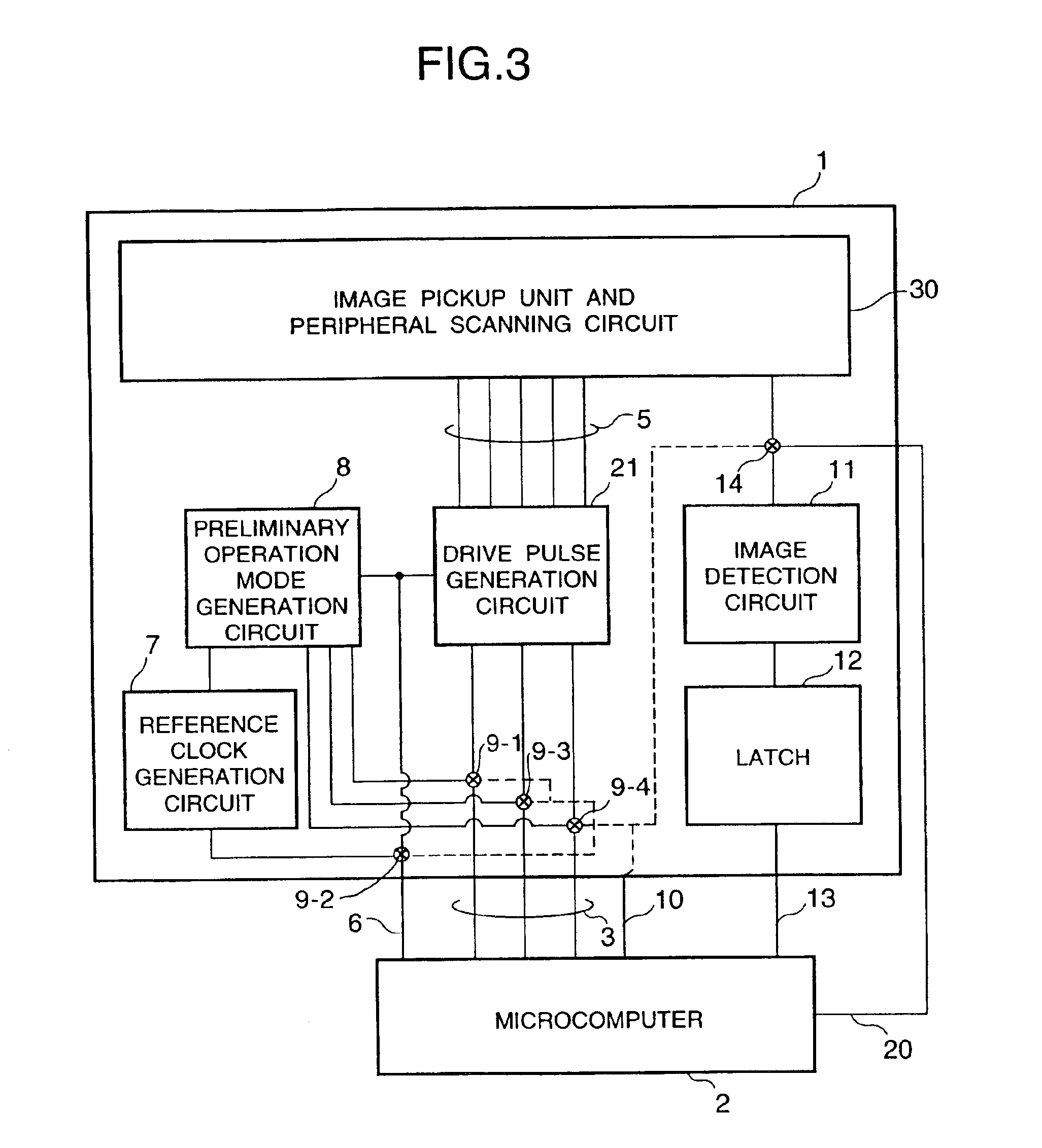
[0032]As explained in the foregoing, the first and second embodiments allow the selection of the drive mode control for the sensor unit 30 by the external microcomputer 2 or by the reference clock generation circuit 7 and the preliminary operation mode generation circuit 8 formed on the image sensor chip 1 or on the drive pulse generation circuit chip 4, whereby it is rendered possible to suspend the operation of the microcomputer 2 during the preliminary operation mode in which the signal processing by the external microcomputer 2 is not required, thereby suppressing the wasteful power consumption in the microcomputer 2.

[0033]Also in the preliminary operation, further suppression of the power consumption is possible since the...


PUM


Abstract

There is provided a solid state image pickup device provided with an image pickup unit containing plural photoelectric conversion elements and a reference clock generation circuit for determining the timing of the drive pulse, wherein the image pickup unit and the reference clock generation circuit are formed in a same semiconductor chip in order to reduce the electric power consumption.

Description

BACKGROUND OF THE INVENTION[0001]1. Field of the Invention[0002]The present invention relates to driving control for a solid state image pickup device.[0003]2. Related Background Art[0004]Conventionally there is known a method for driving a solid state image pickup device as shown in FIG. 1, in which there are shown an image sensor chip 1, a drive timing control device 2 such as a microcomputer (hereinafter called microcomputer) for controlling the image sensor chip 1 by outputting driving pulses therefore, drive mode control wirings 3, drive pulse wirings 5, a reference clock wiring 6, a drive pulse generation circuit 21 provided in the image sensor chip 1, and an image pickup unit / peripheral circuit 22 including plural photoelectric converting elements etc. and a peripheral circuit including horizontal and vertical scanning circuits.[0005]FIG. 2 shows another conventional configuration, wherein shown are an image sensor chip 1 including the image pickup unit / peripheral circuit 22 ...

Claims


Application Information

Patent Timeline
IPC IPC(8): H04N3/15H01L27/146H04N5/335H04N5/376
CPCH04N5/232H04N5/3765H04N5/23245H04N23/661H04N23/651H04N23/667H04N25/745
Inventor SHINOHARA, MAHITO
Owner CANON KK
Why Eureka
Try Eureka