
Cycle portage apparatus and systems thereof having removable tire support

Inactive Publication Date: 2008-03-27
SPORTWORKS NORTHWEST
View PDF8 Cites 14 Cited by
  • Summary
  • Abstract
  • Description
  • Claims
  • Application Information

AI Technical Summary

Benefits of technology

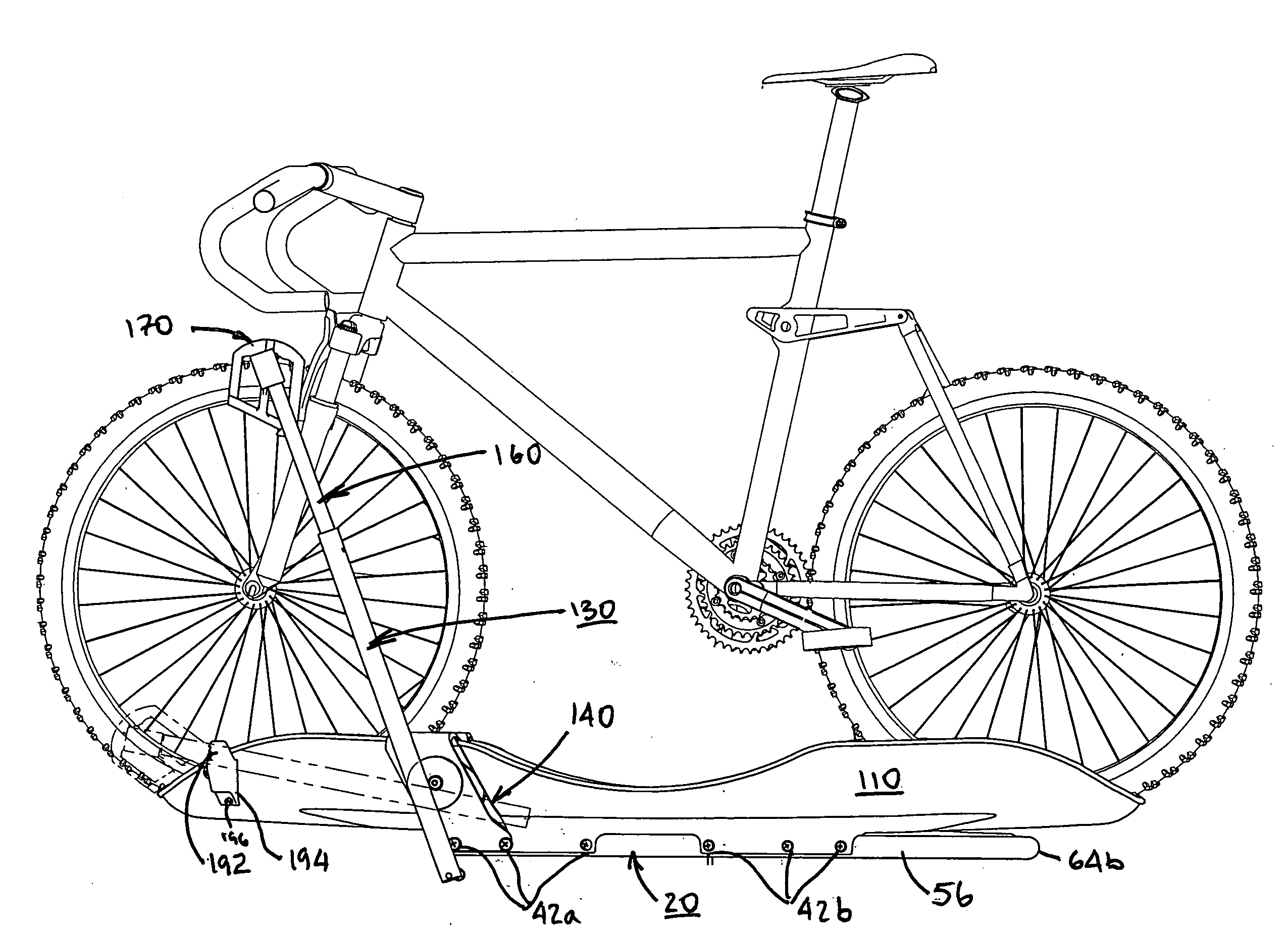
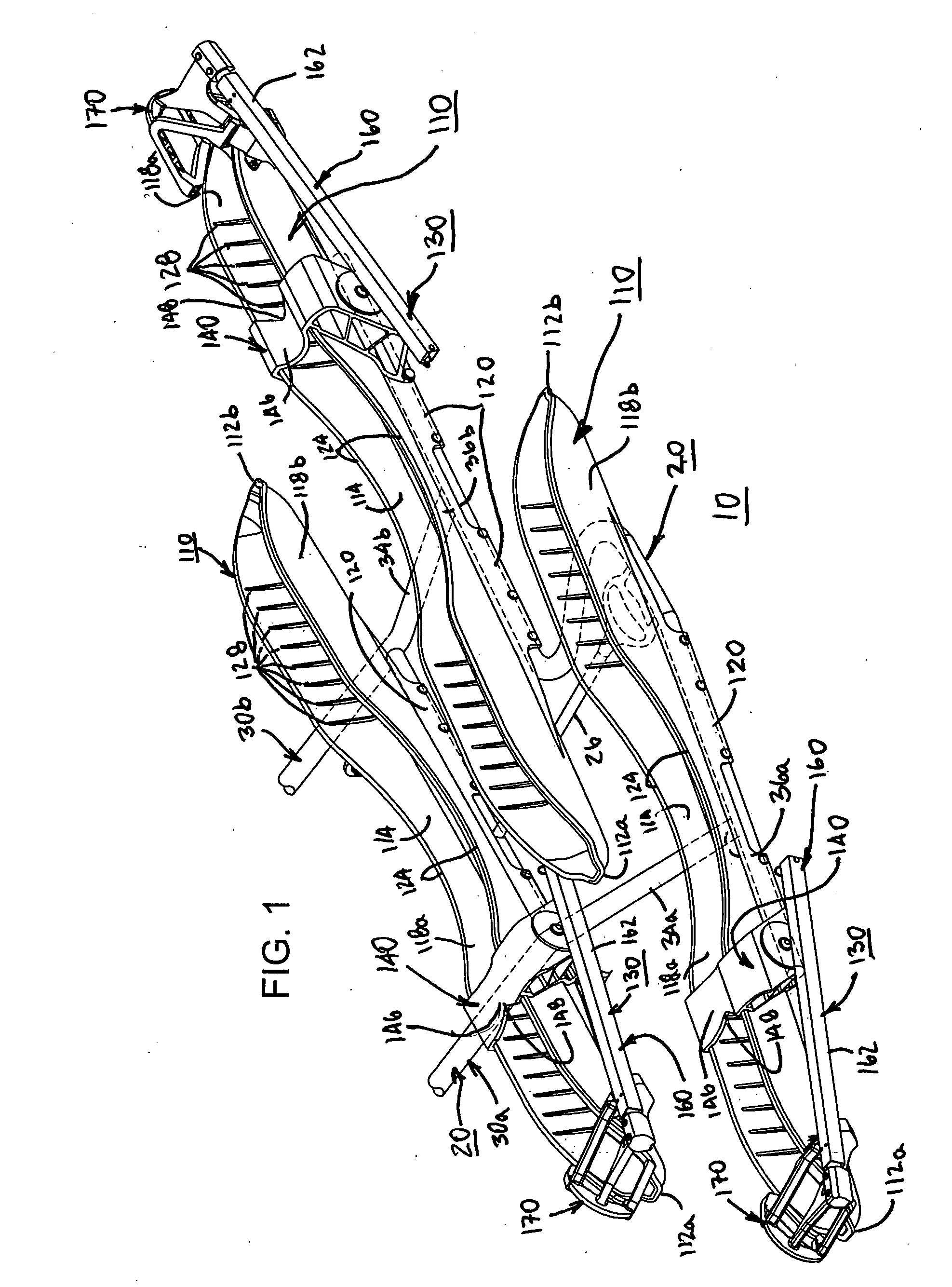
[0006]Each tray embodiment according to the invention may be configured to receive one or multiple tires of a cycle; preferred embodiments provide single trays configured to receive two tires. Furthermore, while the resiliency of the trays according to the invention is greater than that of the frame structural components, and thus is material non-specific, preferred embodiments are constructed from non-metallic materials such as fiber reinforced thermosetting (injection) plastics or thermoformed plastics, which provide the desired levels of performance.
[0008]As previously noted, preferred tray embodiments of the invention may utilize polymeric materials to provide the desired level of performance. In particular, the trays are characterized as resilient, and particularly so over the working range of the anticipated installation. Possessing such qualifications, preferred embodiments of the tire tray resist damage from small impacts that occur during use of the vehicle or system, minimizes damage to objects that impact the tray(s) (persons or property) or are impacted by the tray(s) (front mask of the vehicle). Preferred embodiments of the invention have a flexural modulus of between about 40 KSI and 120 KSI throughout the operation range of the installation, and additionally are not subject to brittle fracture at about −40° C. Material selection, such as thermosetting materials using reaction injection molding, ensure such properties for optimal performance while design geometries enhances load bearing as well as impact deflection properties. The trays need not be constructed from a homogenous material, but may represent hybrid structures both in overall composition, e.g., glass mat and resin, and / or discrete structure, e.g., steel spanning structure mounted to the frame with opposing wheel trays, one for each tire, constructed from a polymer.
[0009]The use of a non-metal (particularly non-steel) tire trays significantly lightens the overall system, thereby decreasing stress at the vehicle mounting interface, provides a corrosion resistant system when used in conjunction with stainless steel frame components and stainless steel fasteners, and in the case of polymer constructed trays, requires no “repair” if reasonably impacted. In many preferred embodiments, a single tire tray having two tire wells weigh approximately 2.5 Kg (5.6 lbs.).
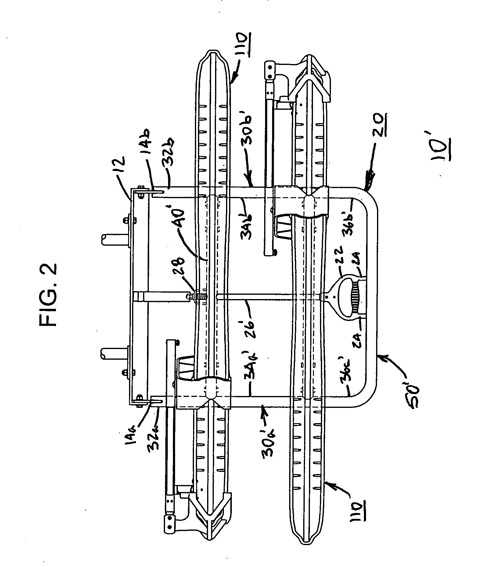
[0011]Mounting flanges may extend from the longitudinal members at the proximal ends thereof or from any cross member positioned adjacent to the proximal ends, and are adapted to engage with a target vehicle, such as a public transit vehicle having a complementary linkage. An assist spring may be used to impart an “upward” or stowed position bias to the frame, thus decreasing the degree of effort a user must exert in order to stow the frame, as is common in most applications. The frame may also comprise a latching assembly to retain the frame in a stowed position and / or a deployed position, as is also common in most applications.
[0014]Further frame embodiments of the invention provide means for establishing a greater number of tire receiving means than the number of transverse frame members, e.g., the first and second cross members. In these embodiments, a single cross member may be longitudinally offset over the lateral direction so that two tire receiving means can be accepted or integrated by or into a single cross member or other laterally extending member. It therefore becomes apparent that the same basic support frame used for two cycle portage applications can be modified through the simple addition or substitution (or adaptation) of a cross member and be transformed into a three cycle portage apparatus. Moreover, if the tire receiving means are removable from the supporting structure, the location of the tire receiving means may be selectable by the user within certain parameters, thus permitting the user to optimally configure the system for a particular use or fitment, e.g., location of headlights and / or turn signals of the equipped vehicle.
[0015]In addition to the foregoing, frame embodiments of the invention may comprises at least one wheel retention assembly for selectively retaining therein a cycle tire that is placed in the tire receiving means. The wheel retention assembly includes a wheel clamp arm, tire jaw (with or without variable tire width accommodation means such as dual contacting surfaces and / or dual channels) and an optional mounting interface. The wheel clamp arm is preferably rotationally mounted either directly or indirectly (via the mounting interface) to the frame, thus providing both flexibility in use by accommodating cycles having disparate wheel diameters as well as efficient stowage when not in use. In one series of embodiments, a mounting interface selectively engages the frame and further provides a pivotal connection location for the support arm. Through this arrangement, a robust linkage between the wheel clamp arm and the frame can be achieved, and in embodiments where the mounting interface engages with the tire receiving means, the mounting interface can also act as a tire chock.

Problems solved by technology

Potential causes of damage to these receiving means included collision with other vehicles or roadway obstacles, parking in the bus overnight storage areabus barn” where high bus density was often required, and the bus wash, which is similar to a car wash but on a larger scale.
In addition, bus drivers typically intentionally impacted the bus wash brush rollers with a significant force to separate them at the start of the wash process, which often caused rack damage.
While the location was selected to provide the greatest fitment to commonly used transit vehicles, it did not satisfactorily address every installation.
Moreover, it was not possible to add an additional bicycle stowage location; interference with existing bicycles would result.

Method used


Image

  • Cycle portage apparatus and systems thereof having removable tire support
  • Cycle portage apparatus and systems thereof having removable tire support
  • Cycle portage apparatus and systems thereof having removable tire support

Examples


Embodiment Construction

[0025]The following discussion is presented to enable a person skilled in the art to make and use the invention. Various modifications to the disclosed embodiments will be readily apparent to those skilled in the art, and the generic principles herein may be applied to other embodiments and applications without departing from the spirit and scope of the present invention as defined by the appended claims. Thus, the present invention is not intended to be limited to the embodiments shown, but is to be accorded the widest scope consistent with the principles and features disclosed herein.

[0026]The following pages will identify the parts of the illustrated embodiments and in conjunction with the appended drawings, their locations. Like parts are given like numbers in the several drawings. Turning then to FIGS. 1-3, two bicycle carrier assembly 10′ and three bicycle carrier assembly 10 are shown. The illustrated carrier assemblies are intended to be mounted to a front bumper of a transi...


PUM


Abstract

Cycle portage apparatus and / or systems employing at least one removable, tire receiving means for retaining a cycle having at least two tires. One series of embodiments is directed to frames adapted to removably receive a tire receiving structure while another series of embodiments is directed to a specific type of such structure, namely, one or more tire trays, and frames optimized to receive them. The preferred applications for embodiments of the invention include transit vehicles having bumper mounted portage frames extending from such bumpers where the frames may be rotated from a stowed position to a deployed position in order to receive at least one cycle, usually a bicycle. Tire tray embodiments according to the invention are constructed from a material having greater resiliency than structural components of the frame.

Description

BACKGROUND OF THE INVENTION[0001]In recent years, public transit has been required to accommodate persons with disabilities and has desired to accommodate persons that would otherwise not use public transportation, such as bicycle riders. In the former case, transit coaches have been adapted to provide lift assistance for users of wheel chairs or who are otherwise mobility impaired. In the later case, coaches have been outfitted with bicycle racks, usually in the front of the coach, whereby users can load and unload their bicycles when taking public transportation.[0002]Since the inception of such bicycle racks, there have been various improvements in both the usability and durability aspects of the technology. Attention has been paid to the bicycle hold-down features of the racks and to the rack's ability to pivot from a deployed position to a stowed position. However, previous bicycle rack designs were generally of a welded steel or aluminum construction with the bicycle supportin...

Claims


Application Information

Patent Timeline
IPC IPC(8): B60R9/10
CPCB60R9/10
Inventor REEVES, MICHAEL K.RAYL, ERIC L.STEWART, GERALD M.
Owner SPORTWORKS NORTHWEST
Learn More