
Method and assembly for evaluating the state of charge of batteries

a battery and state evaluation technology, applied in the field of battery evaluation, can solve the problem of inability to direct physical contact with the actual terminals of the batteries, and achieve the effect of quick and easy evaluation of the state of charge and minimizing the loss of battery charg

Inactive Publication Date: 2005-06-02
TRANSPORT INT POOL
View PDF9 Cites 28 Cited by
  • Summary
  • Abstract
  • Description
  • Claims
  • Application Information

AI Technical Summary

Benefits of technology

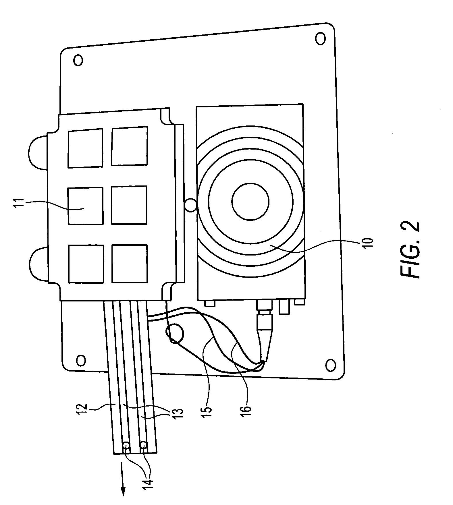
[0011] The invention comprises a method and assembly for quickly and easily evaluating the state of charge of at least one battery without disturbing the batteries. In one embodiment, the batteries are physically installed in a battery-operated device, but the battery terminals are electrically insulated from contact areas of the device by insulating material between the terminals and the contact areas. The purpose of this insulating is to minimize loss of battery charge before the device is put into operation. At the same time, positive and negative battery terminals are each in electrical contact with an electrical conductor, and these conductors extend outward from the battery-operated device. This enables a user to bring the battery terminals into electrical contact with a measuring device, such as a voltmeter, and thereby determine the state of charge of the battery or batteries. If the state of charge is determined to be acceptable, the insulating material may then be removed, bringing the battery terminals into electrical contact with the contact areas of the battery-powered device, thereby activating the device. If the state of charge is found to be unacceptable, the battery may be recharged or replaced or the entire assembly of battery and battery-operated device may be replaced and the state of charge measured again.

Problems solved by technology

In another embodiment, the batteries, with or without a battery-operated device, are either partially or fully enclosed in such a way that direct physical contact with the actual terminals of the batteries is not possible.

Method used


Image

  • Method and assembly for evaluating the state of charge of batteries
  • Method and assembly for evaluating the state of charge of batteries
  • Method and assembly for evaluating the state of charge of batteries

Examples


Embodiment Construction

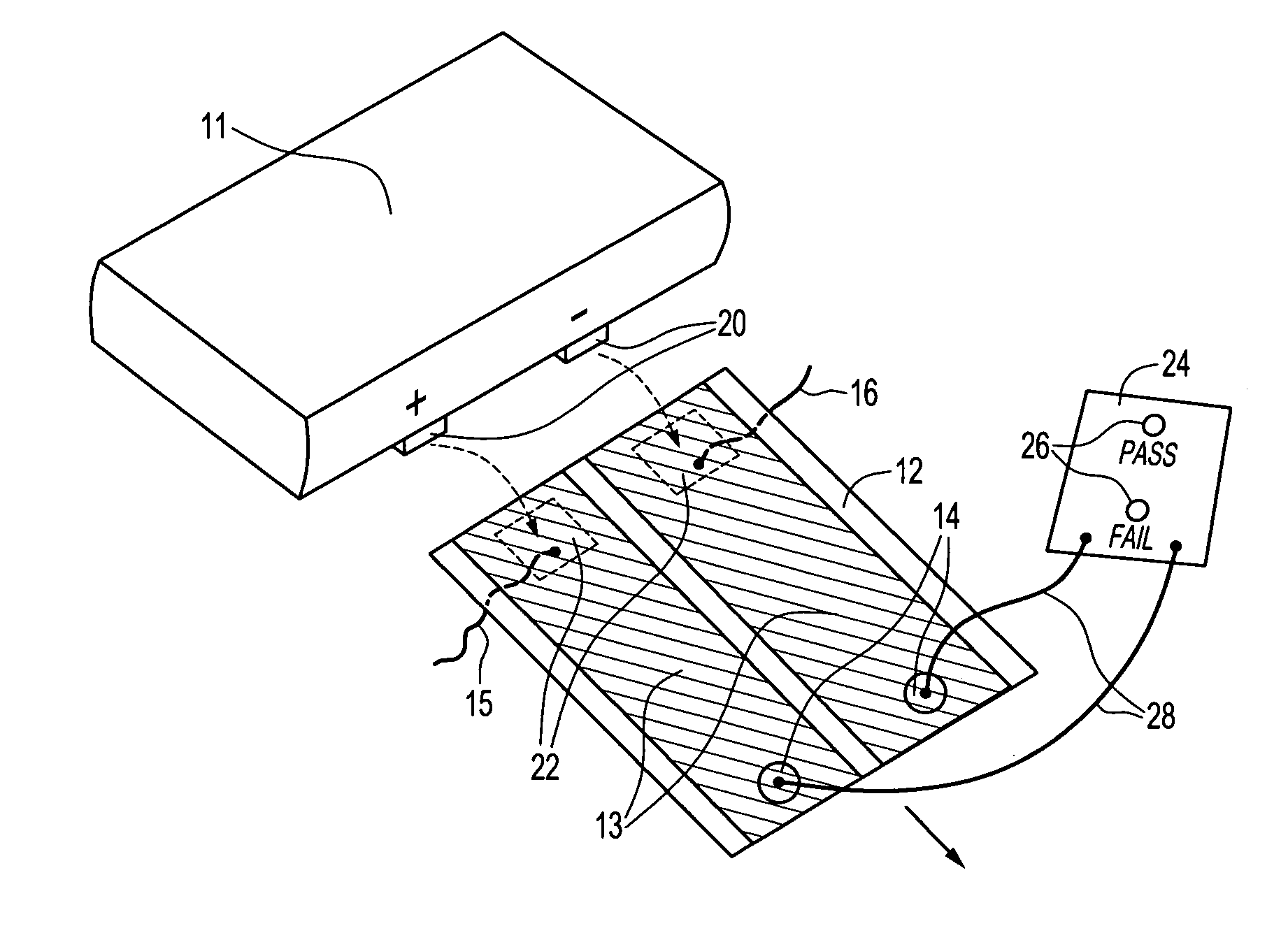
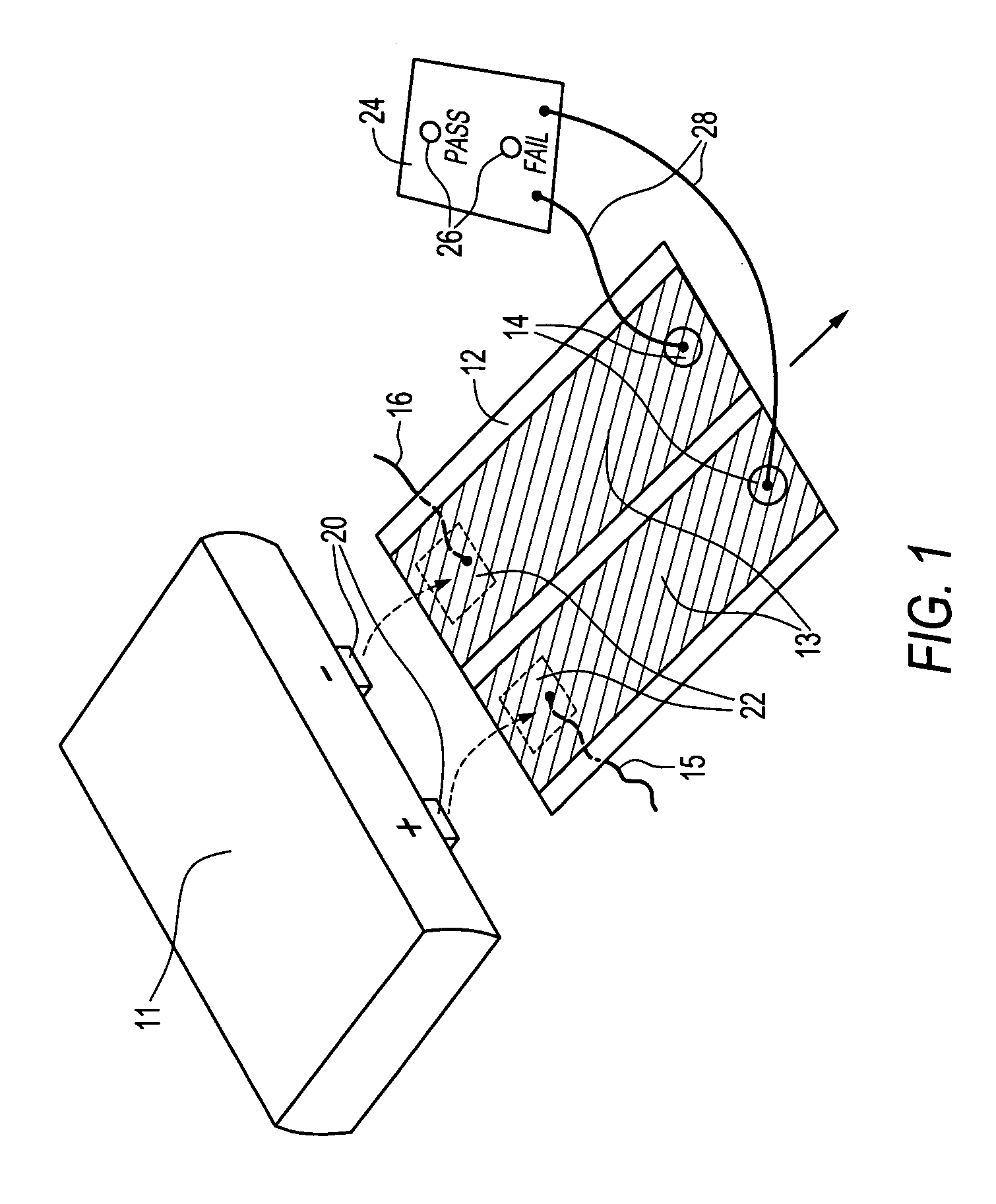
[0016]FIG. 1 is an exploded view illustrating an assembly as an embodiment of the invention. A battery 11 has two terminals 20, one positive and one negative. The terminals make electrical contact with two conductors 13 as indicated by the dashed arrows. The battery terminals 20 are electrically insulated from device contact areas 22 which are connected by wires 15 and 16 to a battery-operated device (not shown). This insulation is achieved by electrically insulating material 12 situated underneath the conductors 13. The state of charge of the battery is determined by bringing the probes 28 of a measuring device 24 into electrical contact with the conductors 13 at the test points indicated by the targets 14. The battery state of charge is displayed by lights 26 on the face of the measuring device 24.

[0017] Once the state of charge is determined, the battery-operated device may be activated by removing the conductors 13 and insulator 12 by pulling in the direction of the solid arrow...


PUM


Abstract

The invention comprises a method and assembly for determining the state of charge of a battery or batteries without disturbing them or removing them from their packaging, or from a device in which they are installed, or from an enclosure preventing direct physical contact with the battery terminals. The battery terminals are electrically insulated from all connections except connections to conductors extending away from the terminals. The state of charge can be determined by attaching a measuring device to the conductors. The conductors and insulators are easily removed, allowing the terminals to come into contact with a battery-powered device.

Description

FIELD OF THE INVENTION [0001] The invention relates to the field of battery evaluation. More specifically, it relates to methods and assemblies for determining the state of charge of one or more batteries without disturbing the surrounding environment of the batteries. BACKGROUND OF THE INVENTION [0002] Battery-operated electrical devices are very common, and in many situations it is desirable to determine the state of charge of the batteries before they are used to provide power to a device. It is also desirable that this determination be made as quickly and easily as possible. The need to assess the state of charge can be especially crucial in situations where a battery has been idle for an extended time period but must then reliably supply power at any given moment. In such situations recharging or replacing defective batteries alone may be too time consuming or even impossible, and replacing an entire electronic or electrical assembly is the only feasible remedy, once the batter...

Claims


Application Information

Patent Timeline
IPC IPC(8): G01R31/36H01M6/50H01M10/48H01M50/583
CPCG01R31/3637H01M10/48H01M6/5044H01M2/34G01R31/388Y02E60/10H01M50/583
Inventor BREEN, THOMAS B.
Owner TRANSPORT INT POOL
Learn More