Modular helmet

a module and helmet technology, applied in the field of helmets, can solve the problems of not being able to guarantee the precise positioning of helmet decorations, the helmet is rather heavy, and the helmet is not flexible, so as to achieve the effect of less expensive manufacturing and developmen

Inactive Publication Date: 2005-06-09
SALOMON SA
View PDF20 Cites 33 Cited by
  • Summary
  • Abstract
  • Description
  • Claims
  • Application Information

AI Technical Summary

Benefits of technology

[0012] An additional object of the invention is also to provide a line of helmets for various uses, but which are less expensive to manufacture and develop,

Problems solved by technology

The disadvantage of this technique is that helmets made in this manner are rather heavy.
Such a helmet has no flexibility and, therefore, unless expensive molds are used, this technique is only used to make light-weight helmets, the covering area of which does not include the zone covering the ears.
Another disadvantage of the so-called “in-mold” technology is that it is not possible to guarantee a precise positioning of the decorations on the helmet.
During the thermoforming and the expansion phase of the polystyrene, it is very difficult to maintain the decoration lines intact, so that a line intended to be straight is blurred on the final helmet.
This decoration technique also has its limits in terms of the quality of the finish because, in view of the imprecise positioning of the sheets in the mold, it is necessary to provide a substantial clearance (several millimeters) between the two sheets.

Method used


Image

  • Modular helmet
  • Modular helmet
  • Modular helmet

Examples


Embodiment Construction

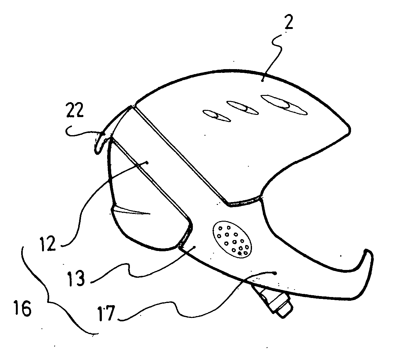
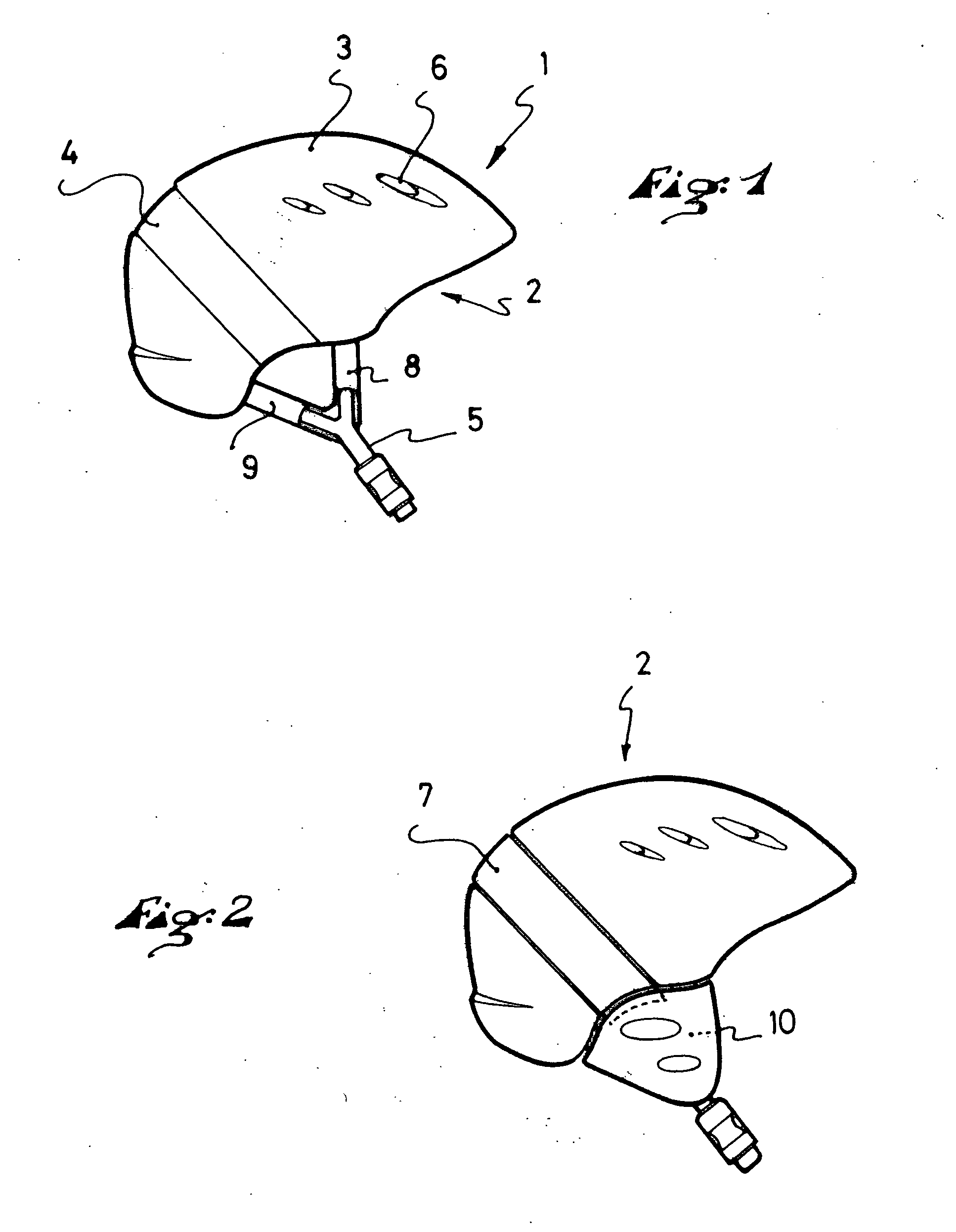
[0027]FIG. 1 illustrates a helmet that has a shell 2 made with “in-mold” technology. In this particular embodiment, the shell 2 comprises a body, in the form of expanded polystyrene, or an expanded polystyrene type of material, molded over an outer skin 3. The outer skin 3, or “micro-shell”, is provided with vents 6, in the form of through-holes, positioned in relation to openings provided in the polystyrene cap. These vents 6 allow fresh air to penetrate inside the helmet. The shell has a channel or groove 4 which runs along its outer surface from one side to the other, from the left temporal area to the right temporal area (shown in FIG. 1). This groove 4, which comprises a slight recess on the outer surface of the helmet, is adapted to receive the arch 7. The helmet is retained on the user's head by means of a chin strap 5 made of a series of flexible straps which have on each side of the helmet a front strap 8 and a back strap 9, which join together to form the chin strap itself...


PUM


Abstract

A helmet for protecting the head having a rigid shell that includes a body, made of an expanded polystyrene type of material, for example, molded over an outer skin, the shell further including a rigid arch device, the arch device includes a headband applied to the shell, each of the ends of the headband being equipped with an ear-covering part. The ear-covering parts can include a foam cushion covered by fabric. The arch device can have two wings which cover the ear-covering parts and which extend the headband and which can also be provided with a chin guard joining the two wings together. The arch device can be either glued or releasably attached to the shell.

Description

CROSS-REFERENCE TO RELATED APPLICATION [0001] This application is based upon French Patent Application No. 03.14352, filed Dec. 8, 2003, the disclosure of which is hereby incorporated by reference thereto in its entirety and the priority of which is hereby claimed under 35 U.S.C. §119.BACKGROUND OP THE INVENTION [0002] 1. Field of the Invention [0003] The invention relates to helmets for protecting the user's head during sporting activities. In particular, the invention relates to helmets to be used for skiing, snowboarding, biking, skateboarding, roller-skating, kayaking, and other sports. [0004] Such helmets are required in sports such as mountain biking, competitive skiing, speed skating or the so-called “aggressive” roller-skating, for example. In addition, the use of such helmets is also strongly recommended for leisure biking and skiing. [0005] 2. Description of Background and Relevant Information [0006] Various techniques have been used in the past to manufacture helmets of t...

Claims


Application Information

Patent Timeline
Patent Type & Authority Applications(United States)
IPC IPC(8): A42B3/16A42B3/22A42B3/32
CPCA42B3/16A42B3/326A42B3/32
Inventor DESARMAUX, PIERREFAVRE-FELIX, HERVE
Owner SALOMON SA
Why Eureka
Try Eureka