Inductively powered apparatus

a technology of inductive power supply and inductive power supply, which is applied in the direction of gas-filled discharge tubes, electric circuit arrangements, and battery arrangement for several simultaneous batteries, etc., can solve the problems of insufficient limited use of inductive power transfer, and significant limitation of overall design and adaptability of inductively powered devices. achieve maximum induced power, control the brightness of light, and efficiently receive power

Inactive Publication Date: 2005-06-09
PHILIPS IP VENTURES BV
View PDF99 Cites 335 Cited by
  • Summary
  • Abstract
  • Description
  • Claims
  • Application Information

AI Technical Summary

Benefits of technology

[0011] In a second aspect, the present invention is directed to an inductive power supply station that is capable of providing power to a plurality of inductive powered devices placed at random location and at random orientations with respect to the primary. The inductive power supply station generally includes a single primary arranged about a receptacle that is capable of receiving randomly placed inductively powered devices. The power supply circuit includes circuitry for adjusting the power supplied to the primary as a function of the inductively powered devices present in the receptacle. In one embodiment, the receptacle is a dish, bowl or similar structure in which one or more lamp assemblies can be placed to provide light. Each lamp assembly includes a secondary that inductively receives power from the primary. The brightness of the light can be controlled by varying the number of lamp assemblies placed in

Problems solved by technology

The use of inductive power transfer has, however, for the most part been limited to niche applications, such as for connections in wet environments.
The limited use of inductive power transfer has been largely the result of power transfer efficiency concerns.
The conventional practice of

Method used


Image

  • Inductively powered apparatus
  • Inductively powered apparatus
  • Inductively powered apparatus

Examples


Embodiment Construction

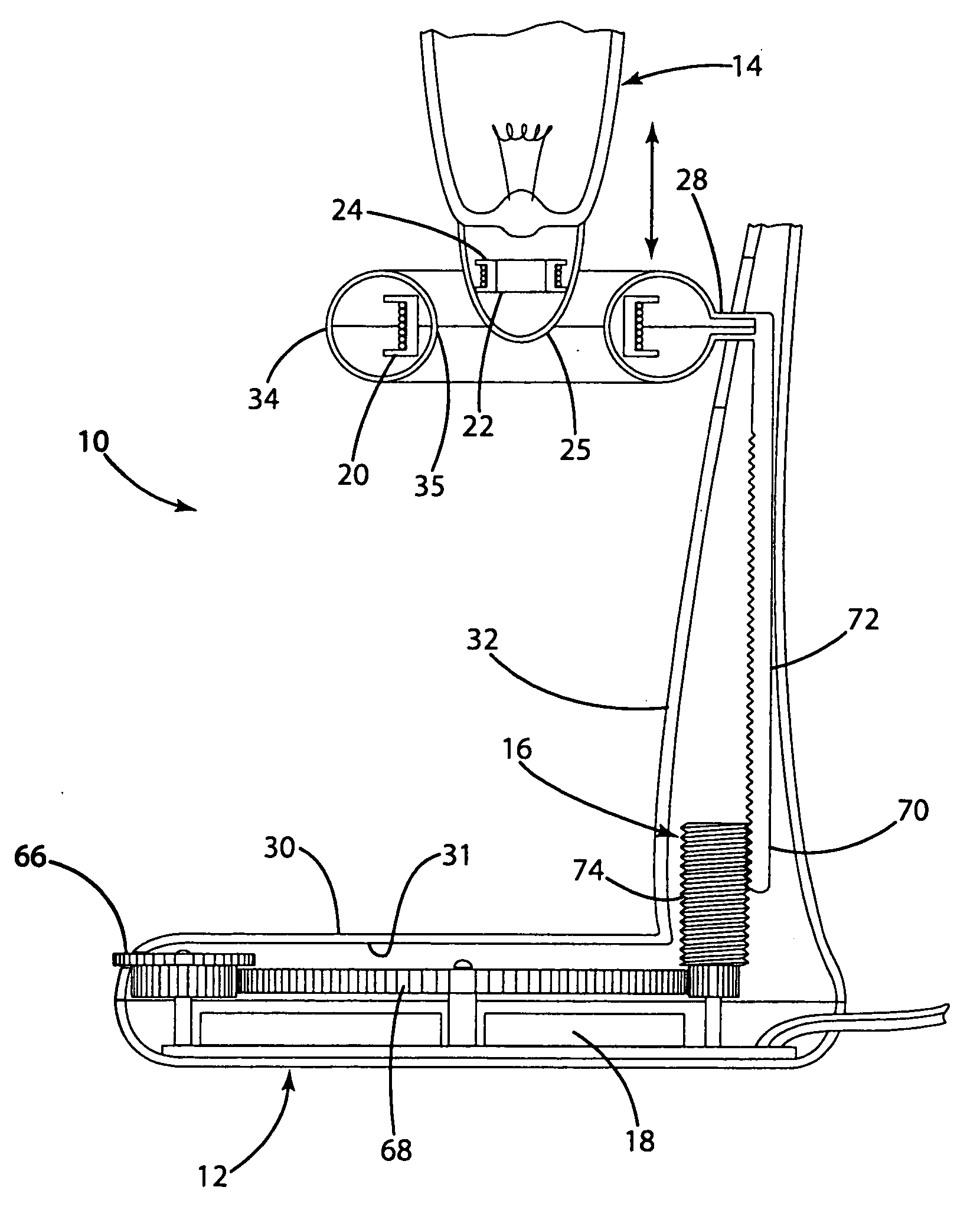
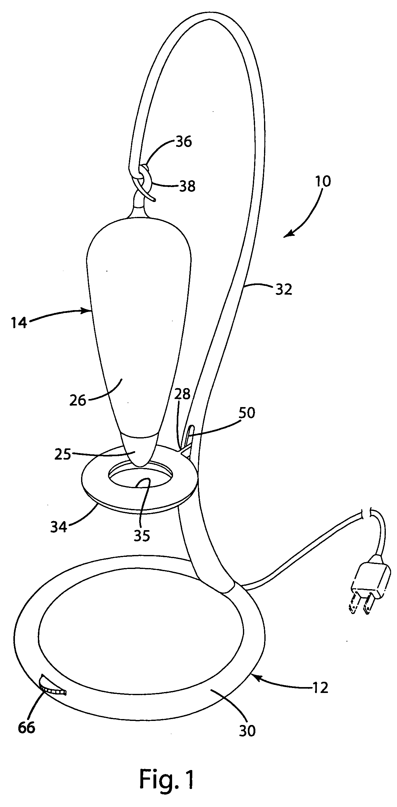
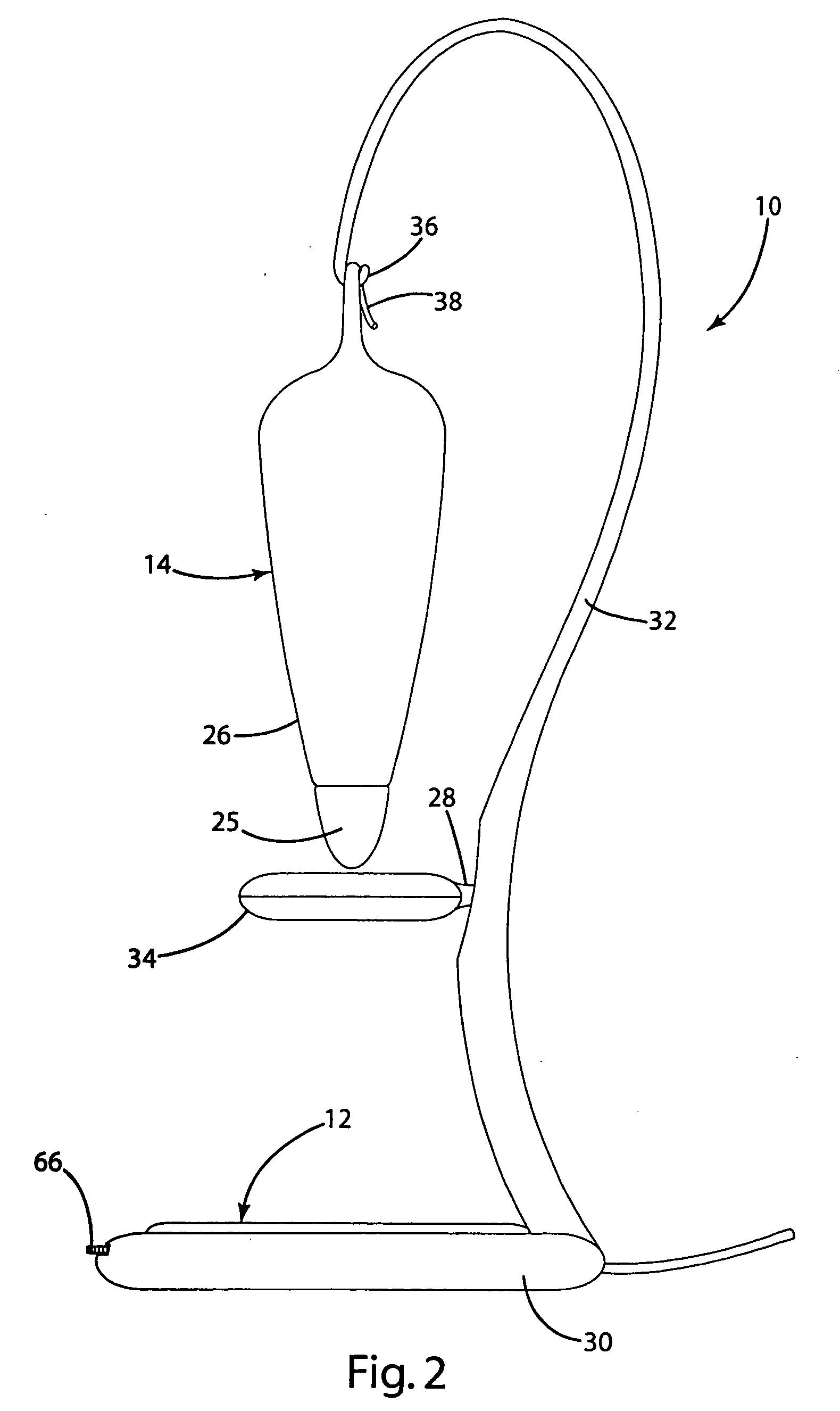
[0059] The present invention is directed to improvements in inductively powered devices. In a first aspect, the present invention provides a inductive coupling in which the relative position between the primary coil (“primary”) and the secondary coil (“secondary”) is selectively varied to permit control over the amount of power transferred to the secondary and consequently to the inductively powered device. This aspect of the invention is described in connection with various lamp configurations, for example, to permit control over the brightness of the light source. This aspect of the invention is also described in connection with other electrically powered devices where control over the amount of power supplied to the inductively powered device is desired. In a second aspect, the present invention is directed to an inductive power supply station. In this aspect, the present invention provides a receptacle for receiving one or more inductively powered devices at random locations and...


PUM


Abstract

An inductive power supply system for providing power to one or more inductively powered devices. The system includes a mechanism for varying the physical distance or the respective orientation between the primary coil and secondary coil to control the amount of power supplied to the inductively powered device. In another aspect, the present invention is directed to an inductive power supply system having a primary coil and a receptacle disposed within the magnetic field generated by the primary coil. One or more inductively powered devices are placed randomly within the receptacle to receive power inductively from the primary coil. The power supply circuit includes circuitry for adjusting the power supplied to the primary coil to optimize operation based on the position and cumulative characteristics of the inductively powered device(s) disposed within the receptacle.

Description

[0001] The present invention is a continuation-in-part of U.S. application Ser. No. 10 / 133,860 entitled “Inductively Powered Lamp Assembly,” which was filed on Apr. 26, 2002 and is a continuation-in-part of U.S. application Ser. No. 90 / 592,194 entitled “Fluid Treatment System,” which was filed on Jun. 12, 2000. [0002] The present application is also a continuation-in-part of U.S. application Ser. No. 10 / 246,155 entitled “Inductively Coupled Ballast Circuit,” which was filed on Sep. 18, 2002 and is a continuation-in-part of U.S. patent application Ser. No. 10 / 175,095 entitled “Fluid Treatment System,” which was filed on Jun. 18, 2002, which is a continuation-in-part of U.S. patent application Ser. No. 09 / 592,194 entitled “Fluid Treatment System,” which was filed on Jun. 12, 2000. U.S. patent application Ser. No. 90 / 592,194 claims the benefit under 35 U.S.C. §119(e) of U.S. provisional patent application Ser. No. 60 / 140,159 entitled “Water Treatment System with an Inductively Coupled ...

Claims


Application Information

Patent Timeline
IPC IPC(8): A61L2/10B01D17/12C02F1/00C02F1/32C02F9/00F21Y101/00H01F5/02H01F38/14H02J7/00H02J7/02H05B37/03H05B39/00H05B41/24H05B41/36
CPCA61L2/10H05B41/36C02F1/008C02F1/325C02F9/005C02F2201/3228C02F2201/326C02F2209/005C02F2209/008C02F2209/40F21S6/00F21V23/02F21V23/04H01F5/02H01F38/14H01F2005/027H01F2005/043H01F2005/046H01J65/048H02J7/0027H02J7/025H02K11/0094H05B37/03H05B39/00H05B41/24C02F1/001H05B47/20H02J50/10H02J50/005H02J7/0044H02J7/0013H02J2310/22C02F9/20H02J50/12H02J50/90
Inventor BAARMAN, DAVID W.MCPHILLIAMY, STEPHEN J.HOUGHTON, CHRISTOPHER
Owner PHILIPS IP VENTURES BV
Why Eureka
Try Eureka