
Driving device of light emitting diode and lighting apparatus using the same

Inactive Publication Date: 2012-06-21
CAL COMP ELECTRONICS +1
View PDF6 Cites 12 Cited by
  • Summary
  • Abstract
  • Description
  • Claims
  • Application Information

AI Technical Summary

Benefits of technology

[0008]The invention is directed to a driving device of an LED and a lighting apparatus using the same, capable of stably controlling the brightness of a light source of an LED bulb by using a dimmer as a TRIAC, so that flicker on the light source of the LED can be avoided.
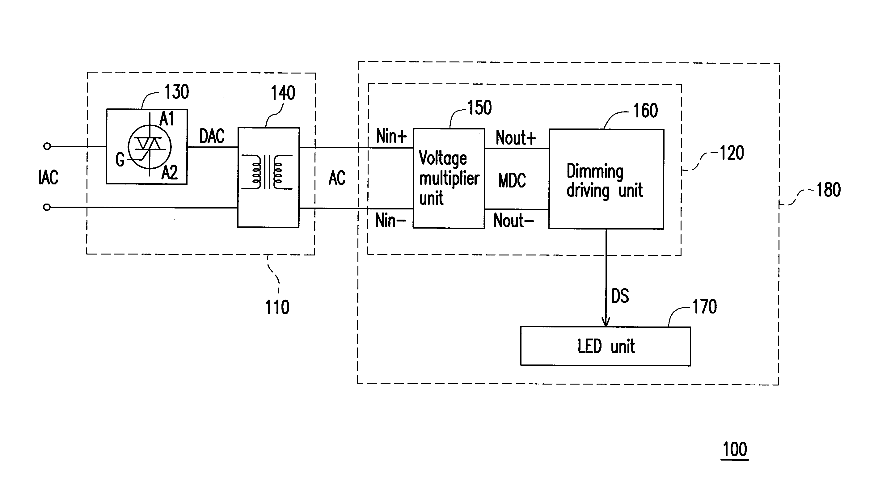
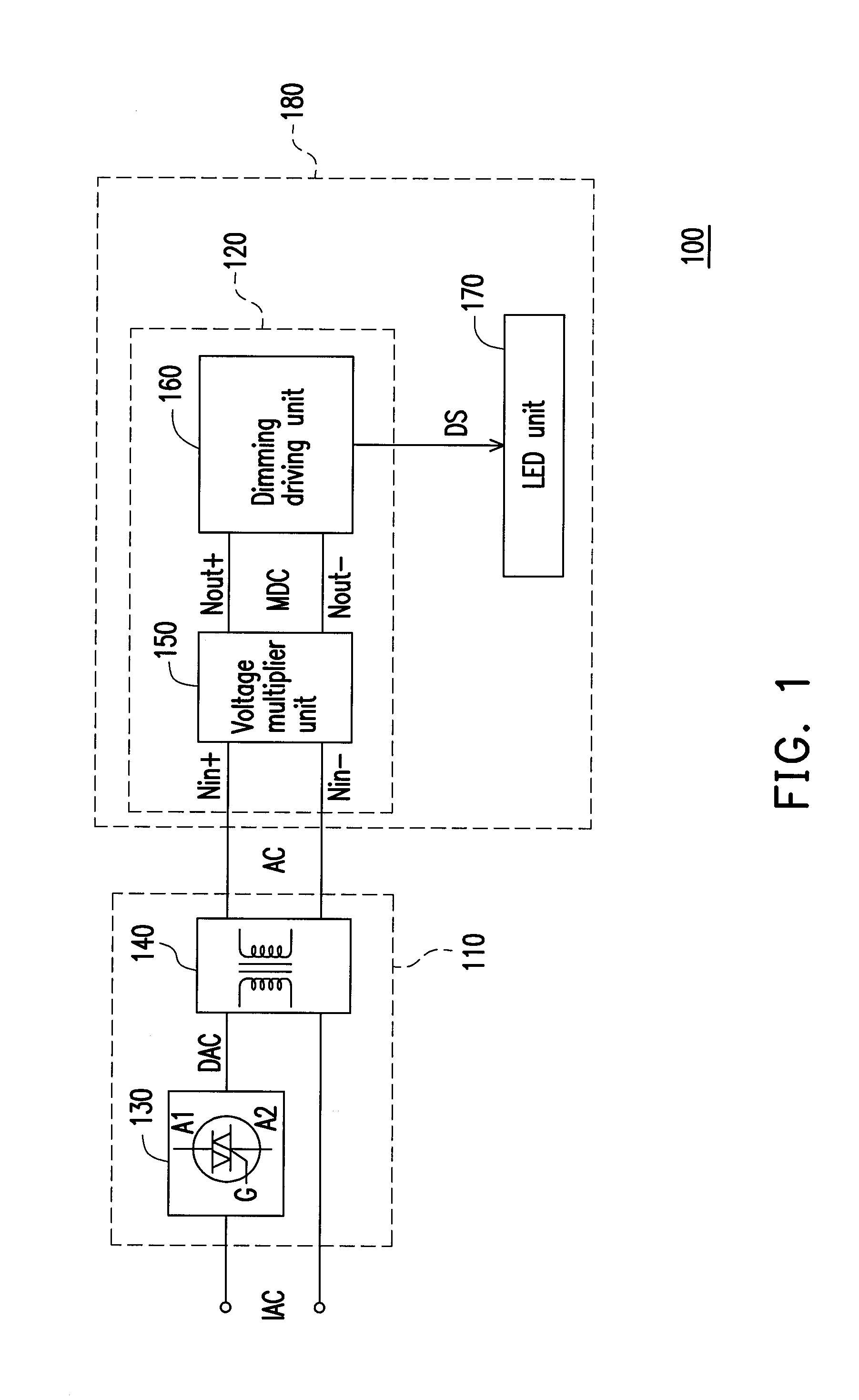
[0013]In view of the above, in the lighting apparatus of the invention, in order to stably control the brightness of an LED unit through an AC power source produced by a dimming control unit, the AC power source is multiplied by a voltage multiplier unit to an operating voltage range of a dimming driving unit. In this manner, not only the dimming driving unit is enabled to successfully drive the LED unit, but also flicker on the light source of the LED unit can be avoided during dimming.

Problems solved by technology

However, since a circuit characteristic of the LED present a capacitance characteristic, when the brightness of the light source of the LED bulb is controlled directly by the dimmer, flicker occurs in most cases.

Method used


Image

  • Driving device of light emitting diode and lighting apparatus using the same
  • Driving device of light emitting diode and lighting apparatus using the same

Examples


Embodiment Construction

[0017]Reference will now be made in detail to the present embodiments of the invention, examples of which are illustrated in the accompanying drawings. Wherever possible, the same reference numbers are used in the drawings and the description to refer to the same or like parts.

[0018]FIG. 1 is a block diagram of a lighting apparatus 100 of an LED according to an embodiment of the present invention. Referring to FIG. 1, in the applications of this embodiment, the lighting apparatus 100 may be considered as a lamp apparatus, for example, a table lamp or a ceiling lamp, a dimming control unit 110 may be considered as a dimming switch and a lamp base frame part of the lighting apparatus 100, and a driving device 120 and an LED unit 170 may be together considered as an LED bulb 180 of the lighting apparatus 100.

[0019]In this embodiment, the dimming control unit 110 includes a dimmer 130 and a transformer unit 140, and the driving device 120 includes a voltage multiplier unit 150 and a dim...


PUM


Abstract

A driving device of a Light Emitting Diode (LED) and a lighting apparatus using the same are provided. The driving device of the LED is adapted for receiving an Alternating Current (AC) power source adjusted by a dimmer and a transformer unit, and includes a dimming driving unit and a voltage multiplier unit. The dimming driving unit receives a driving Direct Current (DC) power source produced by the voltage multiplier unit, so as to drive and adjust the brightness of a light source of an LED unit. The voltage multiplier unit multiplies the AC power source according to a power specification of the dimming driving unit, so as to transform and supply the driving DC power source to the dimming driving unit, and thus flicker on the light source of the LED unit can be avoided during dimming.

Description

CROSS-REFERENCE TO RELATED APPLICATION[0001]This application claims the priority benefit of Taiwan application serial no. 99224346, filed on Dec. 15, 2010. The entirety of the above-mentioned patent application is hereby incorporated by reference herein and made a part of this specification.BACKGROUND OF THE INVENTION[0002]1. Field of the Invention[0003]The present invention relates to a lighting technology of a Light Emitting Diode (LED). Particularly, the invention relates to a driving device of an LED and a lighting apparatus using the same.[0004]2. Description of Related Art[0005]In the lighting technology, a dimmer, for example, a Tri-electrode Alternating Current (AC) switch (TRIAC), is used to adjust the brightness of a lighting apparatus. The dimmer may provide a voltage according to a conducting condition to slightly adjust the light emitting effect of a resistive light emitting element (for example, a halide lamp or a tungsten lamp) of the lighting apparatus. The household...

Claims


Application Information

Patent Timeline
IPC IPC(8): H05B37/02
CPCH05B33/0809H05B45/37H05B45/382
Inventor LIU, YAO-SHENGSU, HUNG-YENWANG, HAO-YUNG
Owner CAL COMP ELECTRONICS
Learn More