Light control apparatus for lighting an organic electroluminescence device and lighting appliance using the same

a light control apparatus and lighting technology, applied in the direction of electric variable regulation, process and machine control, instruments, etc., can solve the problems of wasteful electric power supplied to the light source b>1/b>, and worsen the luminous efficiency, so as to reduce the stress load on the organic el device, increase the brightness of light emission of the lighting appliance using the light control apparatus, and increase the luminous efficiency

Inactive Publication Date: 2013-04-30
PANASONIC CORP
View PDF20 Cites 5 Cited by
  • Summary
  • Abstract
  • Description
  • Claims
  • Application Information

AI Technical Summary

Benefits of technology

[0011]The present invention is conceived to solve the above mentioned problems in the prior art, and a purpose of the invention is to provide a light control apparatus and a lighting appliance using the same, which enable to improve luminous efficiency in light control and to elongate an operating life of a light source.
[0014]According to such configurations, when the capacitive component of the organic EL device is once charged in the light control, discharge of electric charge is prevented by the electric discharge prevention circuit, so that loss of electric power supplied to the light source is small, and thus, luminous efficiency can be increased, even though a switching element of the light control circuit is ON / OFF controlled repeatedly. In addition, since the organic EL device immediately emits lights responding to switching ON of the switching element, rising-up of light flux of the light source becomes precipitous, and brightness of light emission of the lighting appliance using this light control apparatus can be increased. Moreover, surge electric currents due to charge and discharge of the capacitive component do not flow repeatedly in the organic EL device, so that stress loaded on the organic EL device is reduced and an operation life of the light source can be elongated.

Problems solved by technology

In this way, since charge and discharge of the capacitive component of the organic EL device serving as the light source 1 are performed when the switching element Q3 is switched on and off, electric power supplied to the light source 1 is consumed wastefully, and luminous efficiency becomes worse.
Such problems are significant when the switching element Q3 is switched on and off in a high frequency.

Method used


Image

  • Light control apparatus for lighting an organic electroluminescence device and lighting appliance using the same
  • Light control apparatus for lighting an organic electroluminescence device and lighting appliance using the same
  • Light control apparatus for lighting an organic electroluminescence device and lighting appliance using the same

Examples


first embodiment

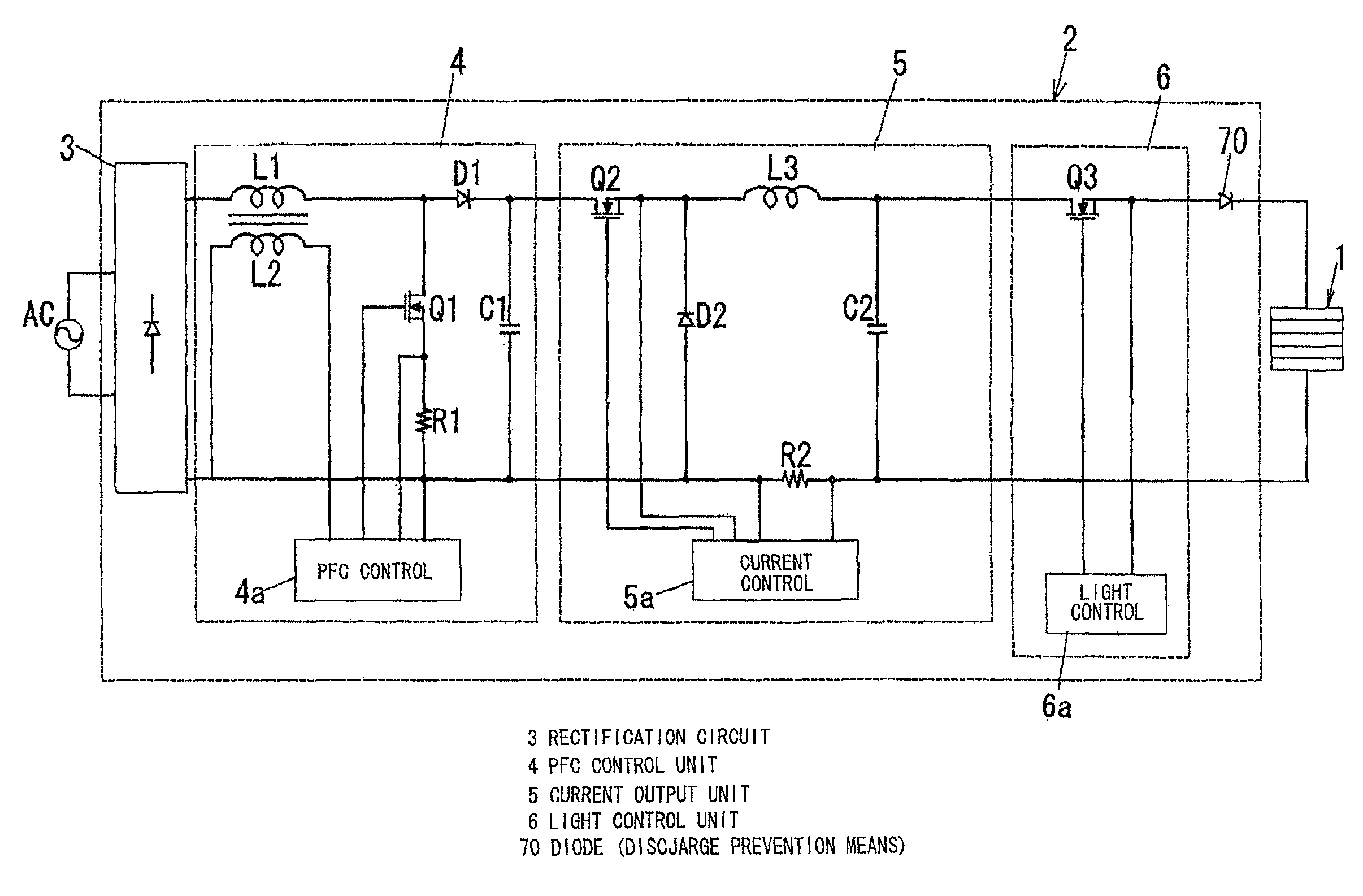
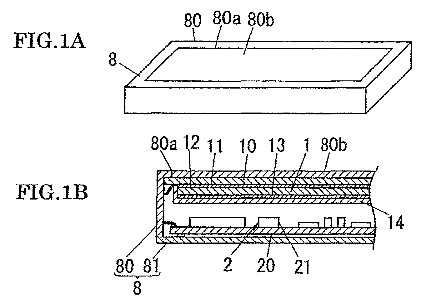
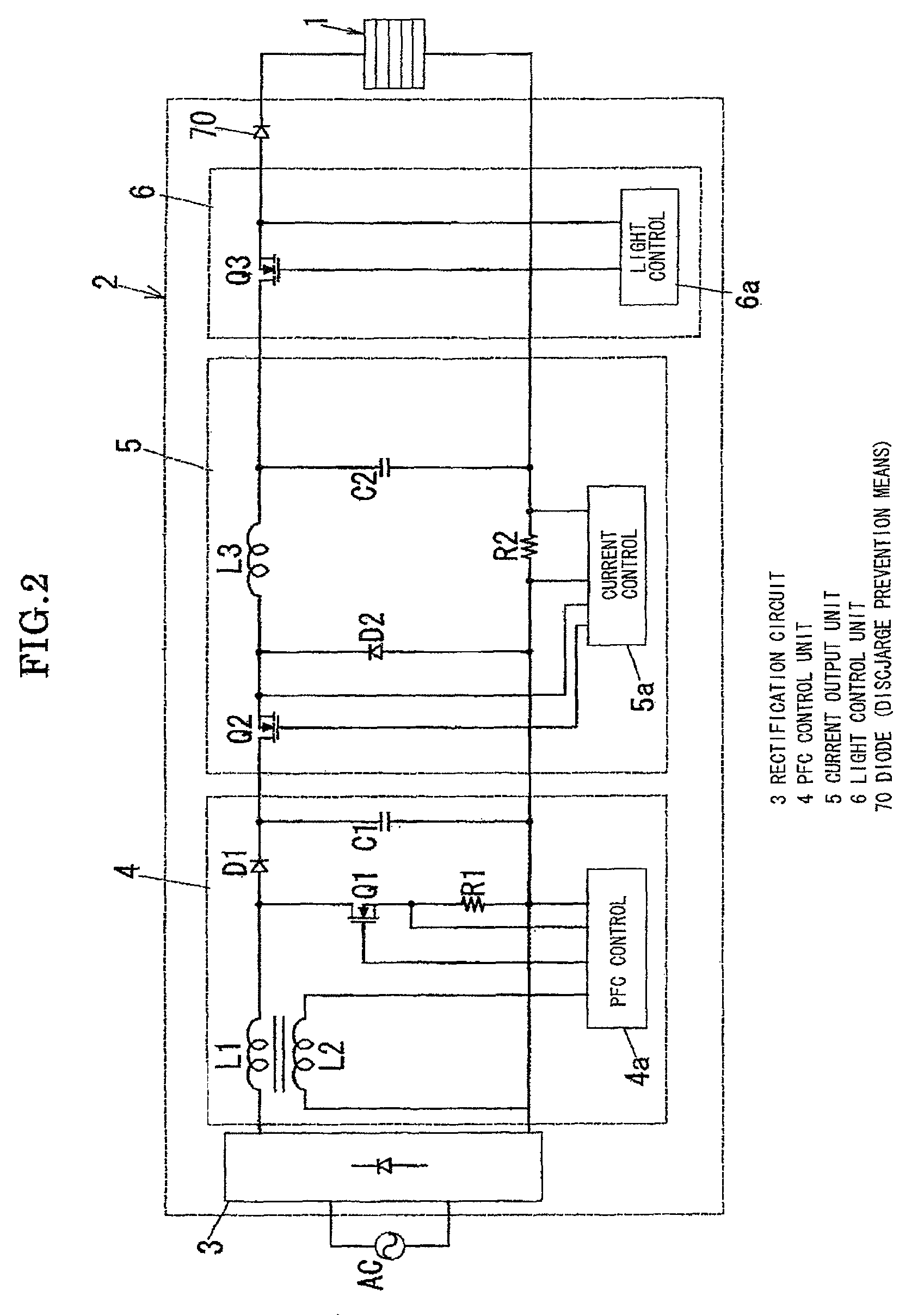
[0027]A light control apparatus and a lighting appliance using the same in accordance with a first embodiment of the present invention are described with reference to figures. FIG. 1A is a perspective illustration showing an appearance of the lighting appliance, and FIG. 1B is a cross sectional illustration showing an inside constitution thereof. As shown in the figures, the lighting appliance comprises a light source 1 configured of an organic EL device, a light control apparatus 2 to control lighting of the light source 1 and a casing 8 for containing the light source 1 and the light control apparatus 2.

[0028]The light source 1 comprises a supporting board 10, a transparent electrode 11 formed on a first face (lower face in the figure) side of the supporting board 10, a light emission layer 12 formed on a surface (lower face) among the surfaces of the transparent electrode 11 opposite to the supporting board 10; a reflection electrode 13 formed of a metal on a surface (lower face)...

second embodiment

[0058]Subsequently a light control apparatus and a lighting appliance using the same in accordance with a second embodiment of the present invention are described. In the second embodiment, it is different that a thyristor 71 is used as an electric discharge prevention circuit in a constitution of a light control apparatus 2 instead of the diode 70, and switching ON / OFF control of the thyristor 71 is performed by a light control unit 6a. The other constitution is the same as that in the first embodiment, the same elements are designated by the same symbols, and thus, the description of them is omitted.

[0059]The thyristor 71 is set between a light control circuit 6 and a light source 1 in a manner so that an anode thereof is connected to an output terminal of the light control circuit 6 and a cathode thereof is connected to the light source, respectively. In addition, a gate of the thyristor 71 is connected to a light control unit 6a. In the thyristor 71, a path between the anode and...

third embodiment

[0065]Subsequently a light control apparatus and a lighting appliance using the same in accordance with a third embodiment of the present invention are described. In the third embodiment, a constitution of a light control circuit 6 is different from that in the above mentioned first embodiment, as shown in FIG. 10. The other constitution is the same as that in the first embodiment, the same elements are designated by the same symbols, and thus, the description of them is omitted.

[0066]The light control circuit 6 in the third embodiment is constituted by a bipolar transistor 72 of n-p-n type, a collector of which is connected to a high electric potential side of a capacitor C2 of an electric current output circuit 5 and an emitter of which is connected to a light source 1, and a light control unit 6a which performs ON / OFF control of the bipolar transistor 72. The light control unit 6a applies a voltage between a base to an emitter of the bipolar transistor 72 based on applied duty ra...


PUM


Abstract

A light control apparatus and a lighting appliance using the same enable increased luminous efficiency in light control and elongated operative life of a light source. The lighting appliance includes a light source and a light control apparatus. The light control apparatus comprises an electric current output circuit that outputs a constant electric current for lighting to a light source configured of an organic electroluminescence device, and a light control circuit that performs light control of the light source by intermittently supplying the constant electric current outputted from the electric current output circuit. The light control apparatus also comprises an electric discharge prevention circuit (diode) that prevents electric discharge of an electric charge charged in a capacitive component of the organic electroluminescence device.

Description

TECHNICAL FIELD[0001]The present invention relates to a light control apparatus for lighting an organic electroluminescence device and a lighting appliance using the same.BACKGROUND ART[0002]In recent years, an organic electroluminescence (Organic Electro-Luminescence, it is called “organic EL”) device attracts attention as a light emitting device. The organic electroluminescence device (hereinafter, it is abbreviated as “organic EL device”) has a characteristic of superior response because a time from start up of power distribution to light emission is very short and brightness instantly varies by varying electric current. In addition, the organic EL device has characteristics that the response hardly varies with temperature, and an angle of field of view thereof is near to 180 degrees. Due to these characteristics, the organic EL device is suitable to surface emission, and thus, it is utilized to a lighting appliance such as a backlight of a liquid crystal display apparatus, recen...

Claims


Application Information

Patent Timeline
Patent Type & Authority Patents(United States)
IPC IPC(8): G05F1/00H05B37/02H05B41/36H05B39/04H05B37/00H05B39/02H05B41/14H05B41/00H05B44/00
CPCH05B33/0896H01L51/50H01L2251/5361H05B45/60Y02B20/30H10K50/00H01L27/0266H10K2102/301
Inventor TAKAKI, HIROFUMIUKEGAWA, SHINMAEHARA, MINORUKONISHI, HIROFUMIOKAWA, MASANAO
Owner PANASONIC CORP
Why Eureka
Try Eureka