Thin switch

Inactive Publication Date: 2005-06-16
ZIPPY TECH
View PDF7 Cites 12 Cited by
  • Summary
  • Abstract
  • Description
  • Claims
  • Application Information

AI Technical Summary

Benefits of technology

[0004] Therefore the primary object of the invention is to resolve the aforesaid disadvantages. The invention provides a thin switch that reduces the overall height of the switch without shortening compression displacement. The thin switch has a trigger assembly which includes an upper button with a bracing section housed in a compartment. The upper button has a coupling trough. A lower button is provided an

Problems solved by technology

Such designs are unnecessary for this type of switch, and do not really contribute to the compression displacement.
As a result,

Method used


Image

  • Thin switch
  • Thin switch
  • Thin switch

Examples


Example

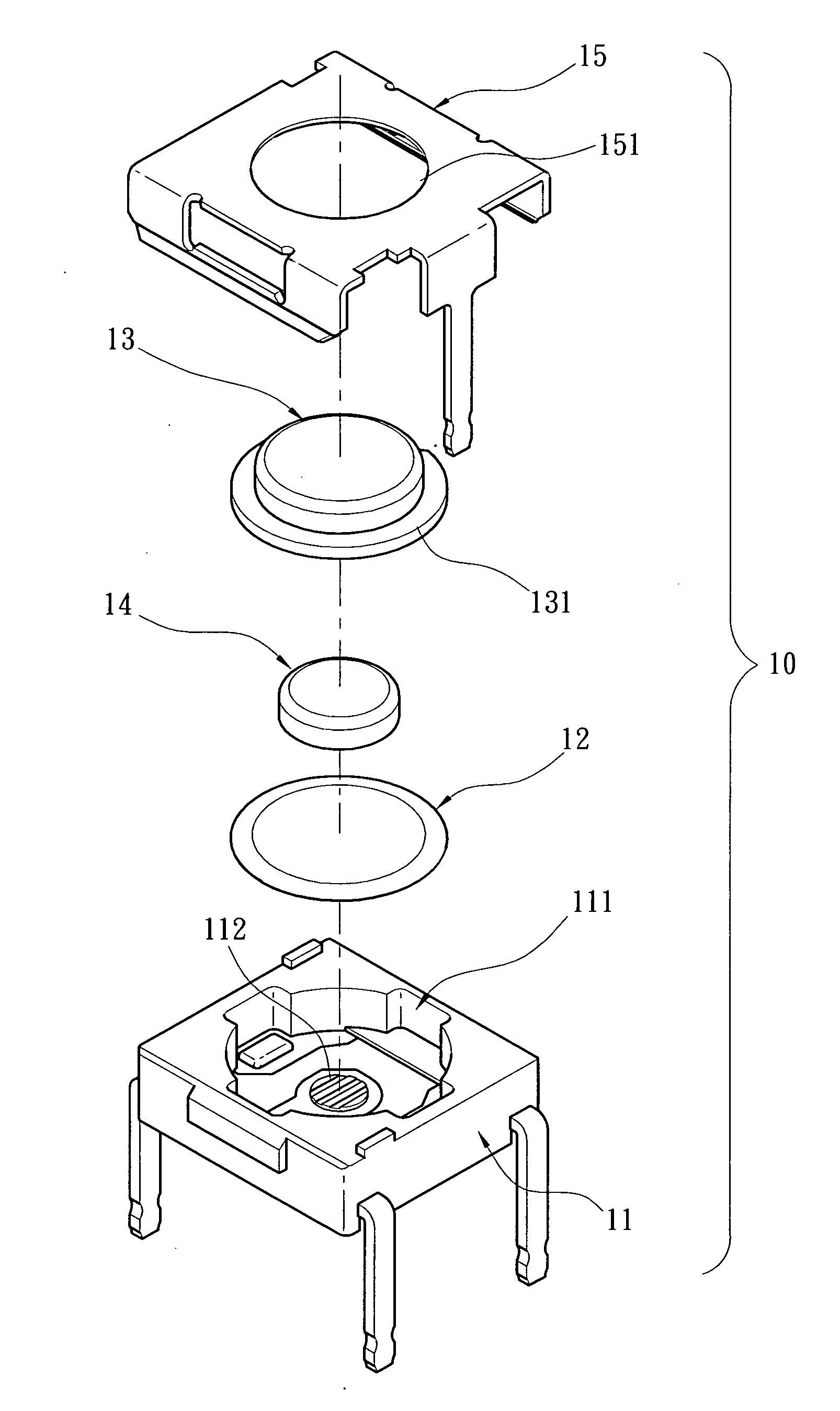
[0014] Please referring to FIGS. 4 and 5A, the switch 10 according to the invention includes a seat 11 which has a hollow compartment 111 with an opening on the upper side. The compartment 111 has an electrode section 112. There is an elastic element 12 above the electrode section 112. Above the elastic element 12 is a trigger assembly which includes an upper button 13 and a lower button 14. The seat 11 is covered by a cap 15 from to seal the compartment 111. The cap 15 has an opening 151 to enable the upper button 13 to extend outwards. The upper button 13 further has a bracing section 131 trapped in the compartment 111 and a coupling trough 132 to hold the compression section 141 of the lower button 14 without exceeding an anchor area of the coupling trough 132. The lower button 14 further has a ram section 142 located between the compression section 141 and the elastic element 12.

[0015] Referring to FIGS. 5A and 5B, when in use, the compression displacement of the trigger assemb...


PUM


Abstract

An improved thin switch aims at reducing overall height of switches without shortening existing compression displacement. It has a trigger assembly which includes an upper button with a bracing section housed in a compartment, a coupling trough, and a lower button with compression section held in the coupling trough without exceeding the anchor portion of the coupling trough. The lower button further has a ram section located between the compression section and the elastic element. The upper button and lower buttons may be deformed as desired to reduce the overall height of the thin switch without affecting existing compression displacement.

Description

FIELD OF THE INVENTION [0001] The present invention relates to an improved thin switch and particularly to a thin switch for reducing the overall height without shortening the compression displacement. BACKGROUND OF THE INVENTION [0002] Thin and lightweight is a prevailing design trend for electronic products these days. Likewise, there is no point to have small components housed in a bulky product. Therefore all aspects of an electronic product should focus these design issues. Mating switch design is no exception. A slimmer design needs to maintain existing compression displacement so as not to affect the feeling of depressing a button. Refer to FIG. 1 for a patent granted to Applicant in ROC patent No. 367086, entitled “Improved touch switch”. It comprises a seat made from an insulating material. The seat has a hollow housing with an opening on the upper side. There is a first conductive electrode located in the center of the housing. There are two second conductive electrodes lo...

Claims


Application Information

Patent Timeline
IPC IPC(8): H01H3/12H01H13/48H01H13/52
CPCH01H13/48H01H13/52H01H2227/036H01H2205/016H01H2203/038
Inventor WANG, YUNG-HUI
Owner ZIPPY TECH
Why Eureka
Try Eureka