Internal multi-band antenna with multiple layers

a multi-band antenna and antenna technology, applied in the field of internal antennas, can solve the problems of antenna breakage and characteristic deterioration, limiting the miniaturization limit, and avoiding recent proposed sars

Inactive Publication Date: 2005-06-16
INFORMATION & COMM UNIV EDUCATIONAL FOUND
View PDF2 Cites 61 Cited by
  • Summary
  • Abstract
  • Description
  • Claims
  • Application Information

AI Technical Summary

Benefits of technology

[0008] In consideration of the above problems of the conventional internal antenna, it is an object of the present invention to provide a new feeding system and antenna structure which is capable of facilitating miniaturization adaptable to a portable terminal for mobile communication and providing

Problems solved by technology

However, although these helical antennas or linear monopole antennas have a merit of omni-directional radiation characteristic, since they are of external type projecting outside the terminals, there is a fear of breakage of antennas and their characteristic deterio

Method used


Image

  • Internal multi-band antenna with multiple layers
  • Internal multi-band antenna with multiple layers
  • Internal multi-band antenna with multiple layers

Examples


Embodiment Construction

[0023] Now, a preferred embodiment of the present invention will be described in detail with reference to the accompanying drawings.

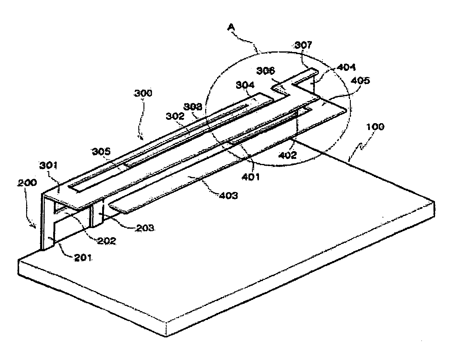
[0024]FIG. 1 is a perspective view of a state where antennas of the present invention are combined to a ground metal plate. As shown in FIG. 1, antennas 300 and 400 are combined to a top portion of one of edges of a ground metal plate 100 via a feeder 200. The feeder 200 is vertically combined to the ground metal plate 100.

[0025] A main radiation patch 300 forming a top side of the antenna has a folded slit patch structure of maze type and is located in parallel to a plane of the ground metal plate 100.

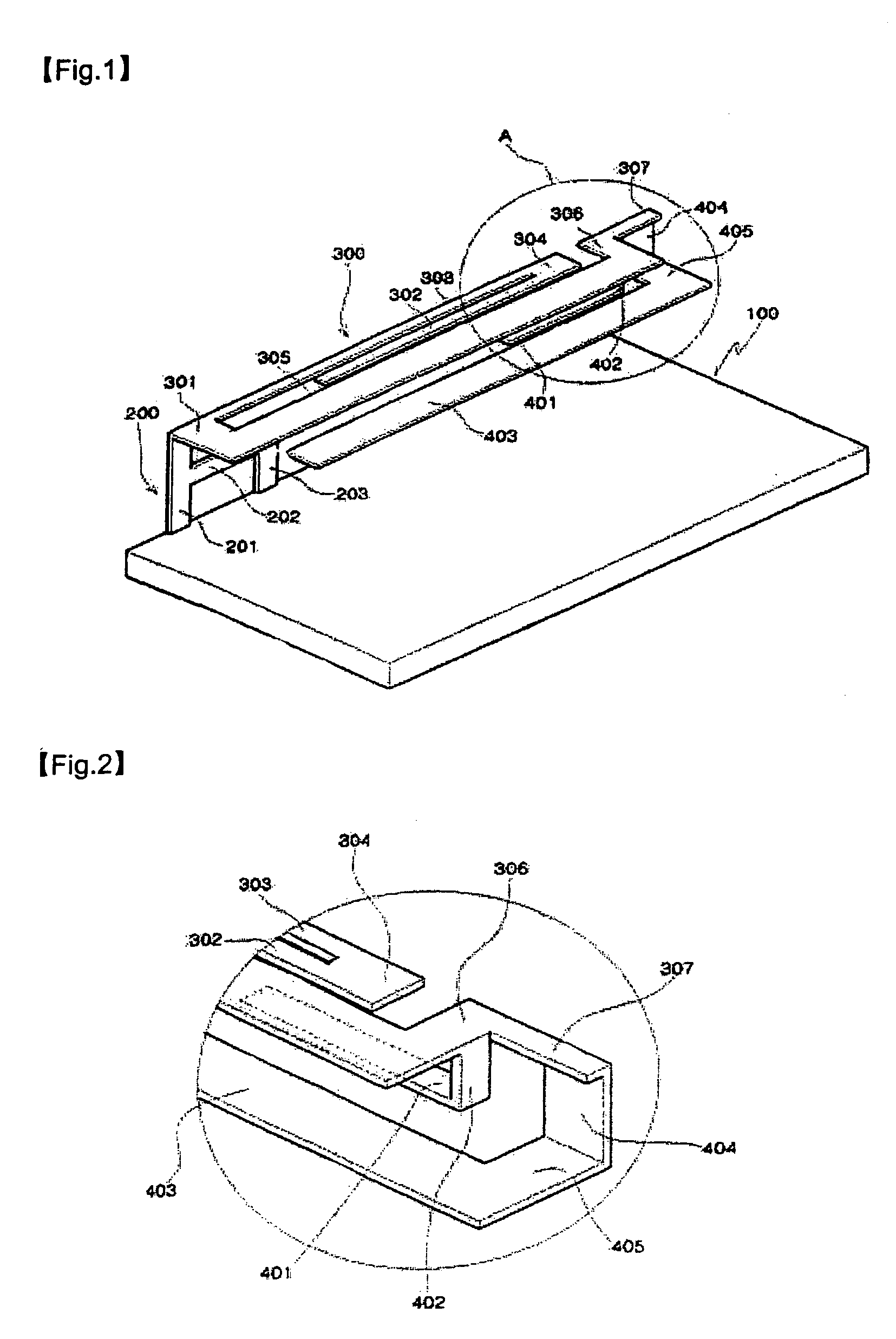
[0026] An auxiliary radiation patch 400 is located in parallel to planes of the main radiation patch 300 and the ground metal plate 100 between the main radiation patch 300 and the ground metal plate 100. The auxiliary radiation patch 400 comprises several strip patches 401 and 403 having different lengths and widths and each of the strip patches 401 a...


PUM


Abstract

The present invention is directed to an internal multi-band antenna with multiple layers. The internal multi-band antenna comprises a main radiation patch for forming an upper side of the antenna, one side of the main radiation patch connected to a feeder, the main radiation patch including a plurality of strips in the same plane and formed by a folded slit patch of maze type; and at least one auxiliary radiation patch bent downwardly at one side of an edge of the main radiation patch and formed in parallel to the main radiation patch between the main radiation patch and a feeder ground plane. In addition, the internal multi-band antenna further comprises a feeder connected to one side of the main radiation patch for transmitting receive signals of the antenna and radiation signals of a body of the portable terminal; a feeder extension extending vertically from a predetermined position in a longitudinal direction of the feeder; and an inverted Y type feeder structure formed by a feeder ground bent at an end of the feeder extension and contacting a ground plane.

Description

BACKGROUND OF THE INVENTION [0001] 1. Field of the Invention [0002] The present invention relates to an internal antenna, and more particularly to an internal antenna with a small-sized structure usable in a multiple band. [0003] 2. Description of the Related Art [0004] Typically, helical antennas or linear monopole antennas are used as antennas for potable terminals. However, although these helical antennas or linear monopole antennas have a merit of omni-directional radiation characteristic, since they are of external type projecting outside the terminals, there is a fear of breakage of antennas and their characteristic deterioration due to an external force. Also, they are vulnerable to recently proposed SAR (Specific Absorption Rate). [0005] A portable terminal antenna for a mobile communication are facing with a user's need for good design, convenience of carrying, service commercial use in a multi-band, light-weighting, and low cost. Accordingly, the portable terminal antenna ...

Claims


Application Information

Patent Timeline
IPC IPC(8): H01Q1/24H01Q5/00H01Q5/371H01Q9/04H01Q9/42
CPCH01Q1/243H01Q5/371H01Q9/42H01Q9/0414H01Q1/24
Inventor KWAK, WON ILPARK, SEONG OOKKO, YOUNG HYUK
Owner INFORMATION & COMM UNIV EDUCATIONAL FOUND
Why Eureka
Try Eureka