AI technical title is built by PatSnap AI team. It summarizes the technical point description of the patent document.
a technology of motion transmission and liquid ejection, which is applied in the field of microelectromechanical liquid ejection devices, can solve the problems of difficult and expensive fabrication of relatively complex components, inability to achieve a working configuration, and constraints on the form of fabrication, etc., to achieve the effect of facilitating resilient deformation
Inactive Publication Date: 2005-06-16
ZAMTEC
View PDF14 Cites 22 Cited by
Summary
Abstract
Description
Claims
Application Information
AI Technical Summary
This helps you quickly interpret patents by identifying the three key elements:
Problems solved by technology
Method used
Benefits of technology
Benefits of technology
[0025] The fulcrum formation and the load formation may define one of the nozzle chamber walls. The roof wall and the load formation may define a gap to permit relative movement of the load formation and the roof wall. The load formation and the roof wall may further define meniscus anchor points to permit liquid in the nozzle chamber to form a meniscus that spans the gap so that the meniscus can define a fluidic seal to inhibit the egress of ink from the nozzle chamber.
Problems solved by technology
As set out in the above referenced applications / patents, the Applicant has spent a substantial amount of time and effort in developing printheads that incorporate micro electromechanical system (MEMS)—based components to achieve the ejection of ink necessary for printing.
A particular difficulty that the Applicant has been faced with is to achieve a suitable interface between a prime mover in the form of an actuator and the moving component.
Such forms of fabrication are subject to constraints since they involve successive deposition and etching techniques.
It follows that MEMS-based devices are usually formed in layers and that components having relatively complex shapes are difficult and expensive to fabricate.
However, the Applicant has found that it is not possible to achieve a working configuration as shown by using MEMS-based fabrication techniques.
In particular, it has been found by the Applicant that such a unitary structure does not lend itself to such fabrication techniques.
Method used
Image
Click on the blue label to locate the original text in one second.
Reading with bidirectional positioning of images and text.
Examples
Embodiment Construction
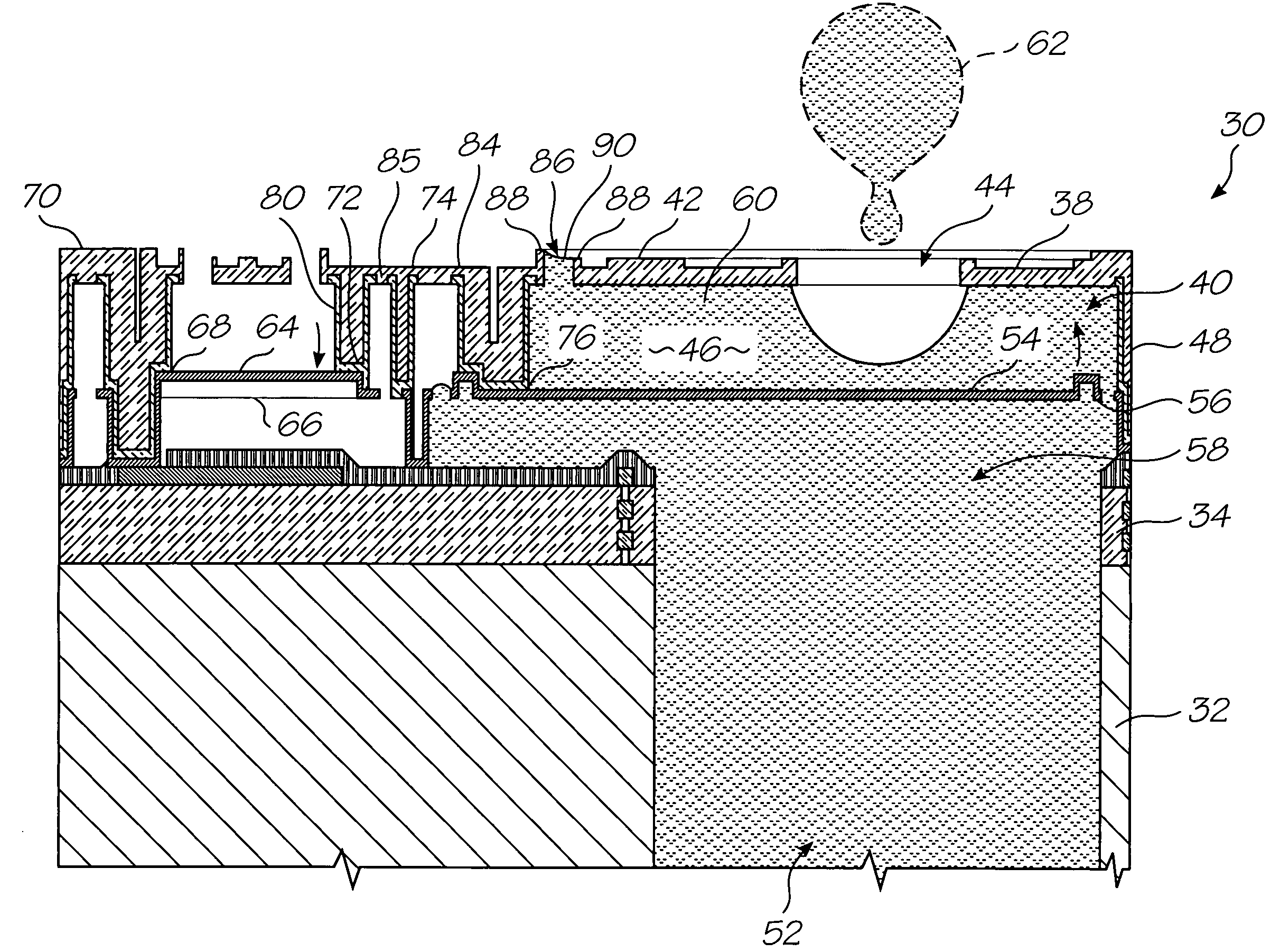
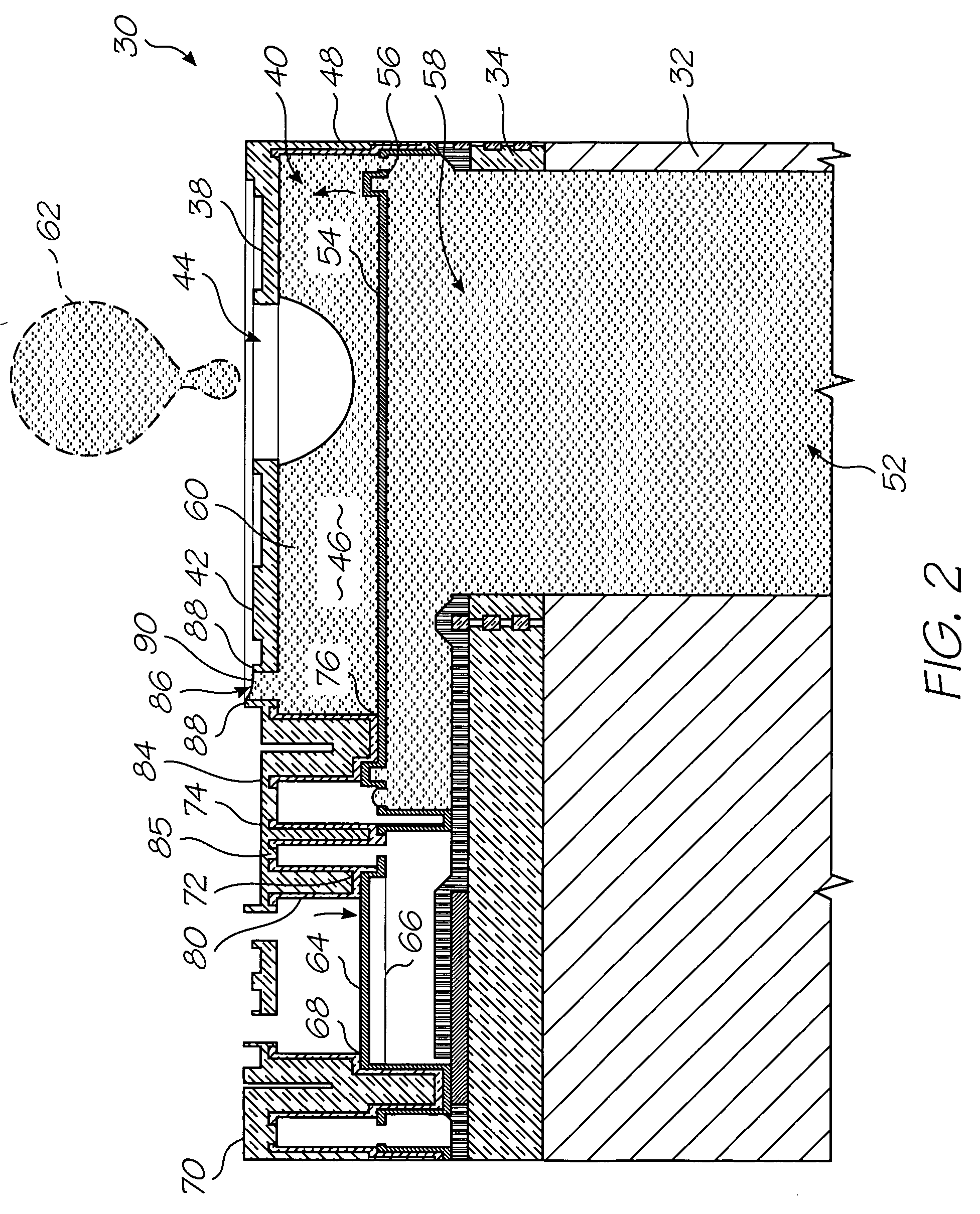
[0041] In FIG. 2, reference numeral 30 generally indicates a nozzle arrangement of a first embodiment of an ink jet printhead chip, in accordance with the invention, for an ink-jet printhead.
[0042] The nozzle arrangement 30 is one of a plurality of such nozzle arrangements formed on a silicon wafer substrate 32 to define the printhead chip of the invention. As set out in the background of this specification, a single printhead can contain up to 84 000 such nozzle arrangements. For the purposes of clarity and ease of description, only one nozzle arrangement is described. It is to be appreciated that a person of ordinary skill in the field can readily obtain the printhead chip by simply replicating the nozzle arrangement 30 on the wafer substrate 32.
[0043] The printhead chip is the product of an integrated circuit fabrication technique. In particular, each nozzle arrangement 30 is the product of a MEMS—based fabrication technique. As is known, such a fabrication technique involves t...
PUM
Property
Measurement
Unit
angular displacement
aaaaa
aaaaa
shapes
aaaaa
aaaaa
electrical
aaaaa
aaaaa
Abstract
A motion-transmitting structure 122, for use in a nozzle arrangement 100 of an ink jet print head chip, the motion transmitting structure 122 comprising an effort formation 124, a lever arm formation 126, and a load formation 128, wherein the lever arm formation 126 is interposed between the effort formation 124 and the load formation 128; and, whereby the motion-transmitting structure 122 interconnects an actuator arm 150 and a paddle 140.
Description
CROSS REFERENCE TO RELATED APPLICATION [0001] This is a Continuation (or Continuation-in-Part) of Ser. No. 10 / 713,093 filed on Nov. 17, 2003 which is a continuation of Ser. No. 10 / 302,275 which is a continuation of Ser. No. 10 / 120,347 which is a CIP of Ser. No. 09 / 112,767 all of which are herein incorporated by reference.STATEMENT REGARDING FEDERALLY SPONSORED RESEARCH OR DEVELOPMENT [0002] Not Applicable FIELD OF THE INVENTION [0003] This invention relates to a micro-electromechanical liquid ejection device. REFERENCED PATENT APPLICATIONS [0004] The following patents / patent applications are incorporated by reference. 6,227,6526,213,5886,213,5896,231,1636,247,79509 / 113,0996,244,6916,257,70409 / 112,7786,220,6946,257,7056,247,7946,234,6106,247,7936,264,3066,241,3426,247,7926,264,3076,254,2206,234,61109 / 112,80809 / 112,8096,239,82109 / 113,0836,247,79609 / 113,12209 / 112,79309 / 112,79409 / 113,12809 / 113,1276,227,6536,234,6096,238,0406,188,4156,227,6546,209,9896,247,79109 / 112,7646,217,15309 / 112,7...
Claims
Application Information
Patent Timeline
Application Date:The date an application was filed.
Publication Date:The date a patent or application was officially published.
First Publication Date:The earliest publication date of a patent with the same application number.
Issue Date:Publication date of the patent grant document.
PCT Entry Date:The Entry date of PCT National Phase.
Estimated Expiry Date:The statutory expiry date of a patent right according to the Patent Law, and it is the longest term of protection that the patent right can achieve without the termination of the patent right due to other reasons(Term extension factor has been taken into account ).
Invalid Date:Actual expiry date is based on effective date or publication date of legal transaction data of invalid patent.
Patent Type & AuthorityApplications(United States)

