Printhead chip that incorporates micro-mechanical lever mechanisms
What is AI technical title?
AI technical title is built by PatSnap AI team. It summarizes the technical point description of the patent document.
a micro-mechanical lever mechanism and printhead technology, applied in the field of micro-electromechanical liquid ejection devices, can solve the problems of difficult and expensive fabrication of relatively complex components, inability to achieve working configurations, and constraints on the form of fabrication
Inactive Publication Date: 2006-11-07
ZAMTEC +1
View PDF79 Cites 18 Cited by
Summary
Abstract
Description
Claims
Application Information
AI Technical Summary
This helps you quickly interpret patents by identifying the three key elements:
Problems solved by technology
Method used
Benefits of technology
Benefits of technology
[0026]The fulcrum formation and the load formation may define one of the nozzle chamber walls. The roof wall and the load formation may define a gap to permit relative movement of the load formation and the roof wall. The load formation and the roof wall may further define meniscus anchor points to permit liquid in the nozzle chamber to form a meniscus that spans the gap so that the meniscus can define a fluidic seal to inhibit the egress of ink from the nozzle chamber.
Problems solved by technology
A particular difficulty that the Applicant has been faced with is to achieve a suitable interface between a prime mover in the form of an actuator and the moving component.
Such forms of fabrication are subject to constraints since they involve successive deposition and etching techniques.
It follows that MEMS-based devices are usually formed in layers and that components having relatively complex shapes are difficult and expensive to fabricate.
However, the Applicant has found that it is not possible to achieve a working configuration as shown by using MEMS-based fabrication techniques.
In particular, it has been found by the Applicant that such a unitary structure does not lend itself to such fabrication techniques.
Method used
Image
Click on the blue label to locate the original text in one second.
Reading with bidirectional positioning of images and text.
Examples
Embodiment Construction
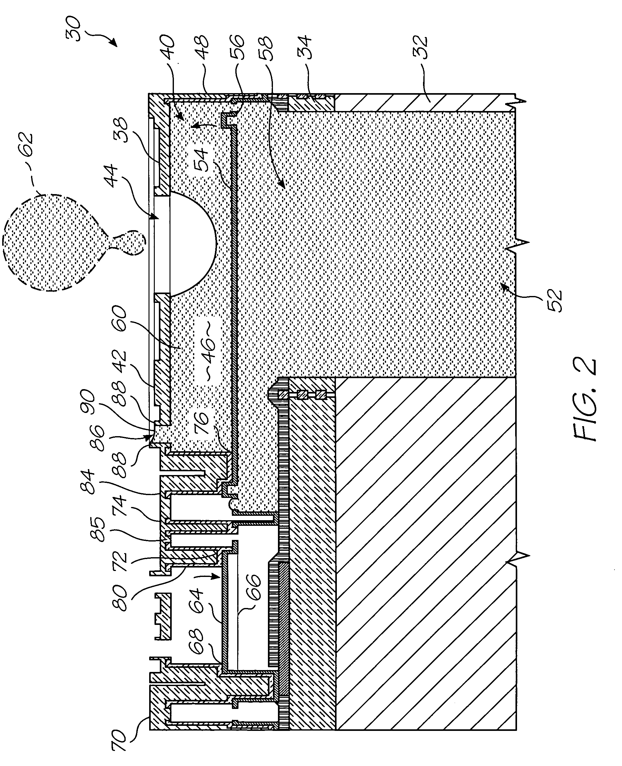
[0042]In FIG. 2, reference numeral 30 generally indicates a nozzle arrangement of a first embodiment of an ink jet printhead chip, in accordance with the invention, for an inkjet printhead.
[0043]The nozzle arrangement 30 is one of a plurality of such nozzle arrangements formed on a silicon wafer substrate 32 to define the printhead chip of the invention. As set out in the background of this specification, a single printhead can contain up to 84 000 such nozzle arrangements. For the purposes of clarity and ease of description, only one nozzle arrangement is described. It is to be appreciated that a person of ordinary skill in the field can readily obtain the printhead chip by simply replicating the nozzle arrangement 30 on the wafer substrate 32.
[0044]The printhead chip is the product of an integrated circuit fabrication technique. In particular, each nozzle arrangement 30 is the product of a MEMS-based fabrication technique. As is known, such a fabrication technique involves the dep...
PUM
Abstract
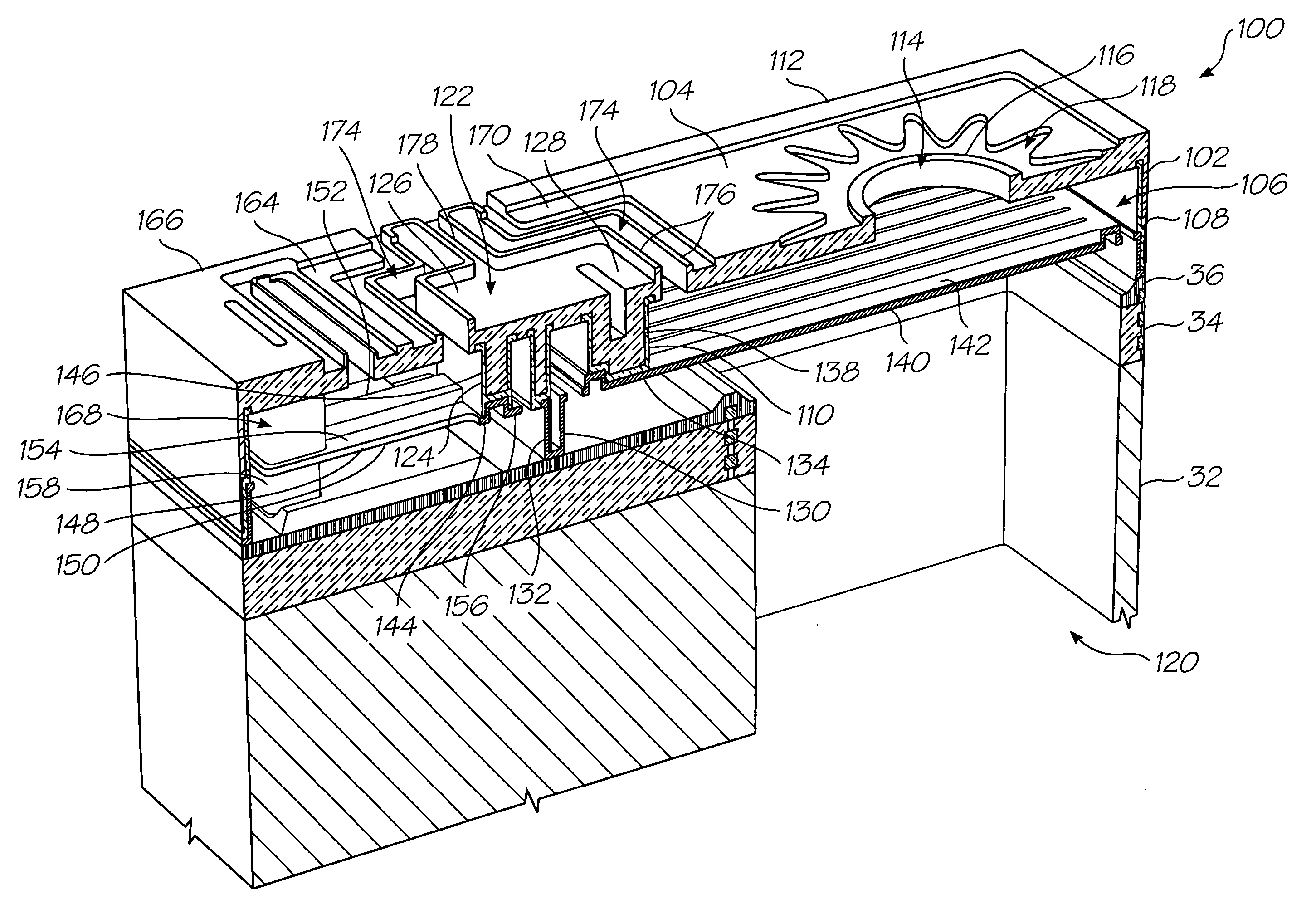
A printhead chip includes a substrate that incorporates drive circuitry and defines a plurality of ink inlet channels. Nozzle chamber structures are positioned on the substrate and define nozzle chambers in fluid communication with respective ink inlet channels and ink ejection ports in fluid communication with respective nozzle chambers. Elongate micro-electromechanical actuators are fast with the substrate at first ends to be connected to the drive circuitry so that second ends are displaceable reciprocally with respect to the substrate on receipt of electrical signals from the drive circuitry. Ink ejection members are positioned in respective nozzle chambers and are displaceable with respect to the substrate to eject ink from associated ink ejection ports. Micro-mechanical lever mechanisms are interposed between respective actuators and ink displacement members so that displacement of the actuators is transmitted to the ink displacement members.
Description
CROSS REFERENCES TO RELATED APPLICATIONS[0001]This application is a continuation application of U.S. application Ser. No. 10 / 713,093 filed Nov. 17, 2003 now U.S. Pat. No. 7,008,046 which is a Continuation Application of U.S. application Ser. No. 10 / 302,275 filed Nov. 23, 2002, now U.S. Pat. No. 6,669,332 which is a Continuation of U.S. application Ser. No. 10 / 120,347 filed Apr. 12, 2002, now U.S. Pat. No. 6,540,332 which is a CIP of Ser. No. 09 / 112,767 filed Jul. 10, 1998, now U.S. Pat. No. 6,416,167 all of which are herein incorporated by reference.STATEMENT REGARDING FEDERALLY SPONSORED RESEARCH OR DEVELOPMENT[0002]Not ApplicableFIELD OF THE INVENTION[0003]This invention relates to a micro-electromechanical liquid ejection device.REFERENCED PATENT APPLICATIONS[0004]The following patents / patent applications are incorporated by reference.[0005]6,227,6526,213,5886,213,5896,231,1636,247,79509 / 113,0996,244,6916,257,70409 / 112,7786,220,6946,257,7056,247,7946,234,6106,247,7936,264,3066,24...
Claims
Application Information
Patent Timeline
Application Date:The date an application was filed.
Publication Date:The date a patent or application was officially published.
First Publication Date:The earliest publication date of a patent with the same application number.
Issue Date:Publication date of the patent grant document.
PCT Entry Date:The Entry date of PCT National Phase.
Estimated Expiry Date:The statutory expiry date of a patent right according to the Patent Law, and it is the longest term of protection that the patent right can achieve without the termination of the patent right due to other reasons(Term extension factor has been taken into account ).
Invalid Date:Actual expiry date is based on effective date or publication date of legal transaction data of invalid patent.

