Apparatus and method for image-classifying, and recording medium storing computer-readable program for the same

Active Publication Date: 2005-06-16
SOVEREIGN PEAK VENTURES LLC
View PDF8 Cites 56 Cited by
  • Summary
  • Abstract
  • Description
  • Claims
  • Application Information

AI Technical Summary

Benefits of technology

[0012] An object of the present invention is to provide an image-classifying apparatus that can appropriately cl

Problems solved by technology

However, the user cannot see all images within a limited time in many cases.
However, an expected image group of elements that the user thinks belongs to one event and a generated image

Method used


Image

  • Apparatus and method for image-classifying, and recording medium storing computer-readable program for the same
  • Apparatus and method for image-classifying, and recording medium storing computer-readable program for the same
  • Apparatus and method for image-classifying, and recording medium storing computer-readable program for the same

Examples


first embodiment

[0072] First, an image-classifying apparatus, an image-classifying method, and a program in the first embodiment of the present invention are explained. An image-classifying system of the first embodiment comprises: the image-classifying apparatus; a shooting apparatus; and a display apparatus.

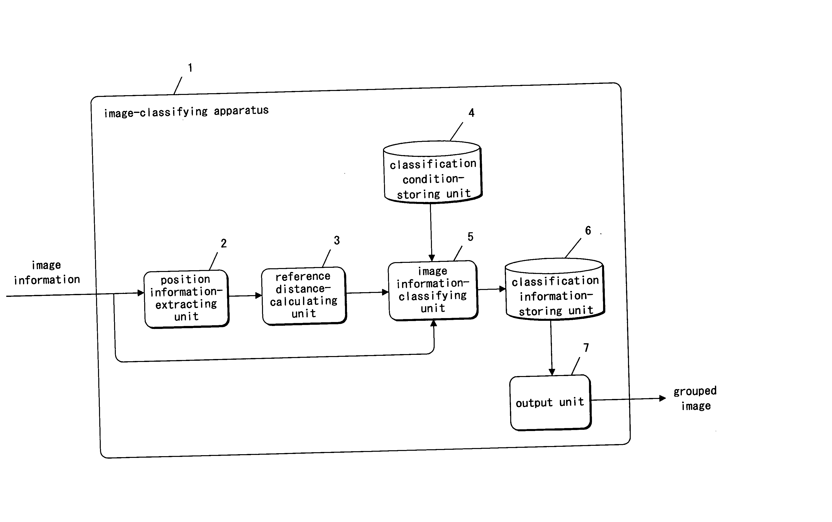
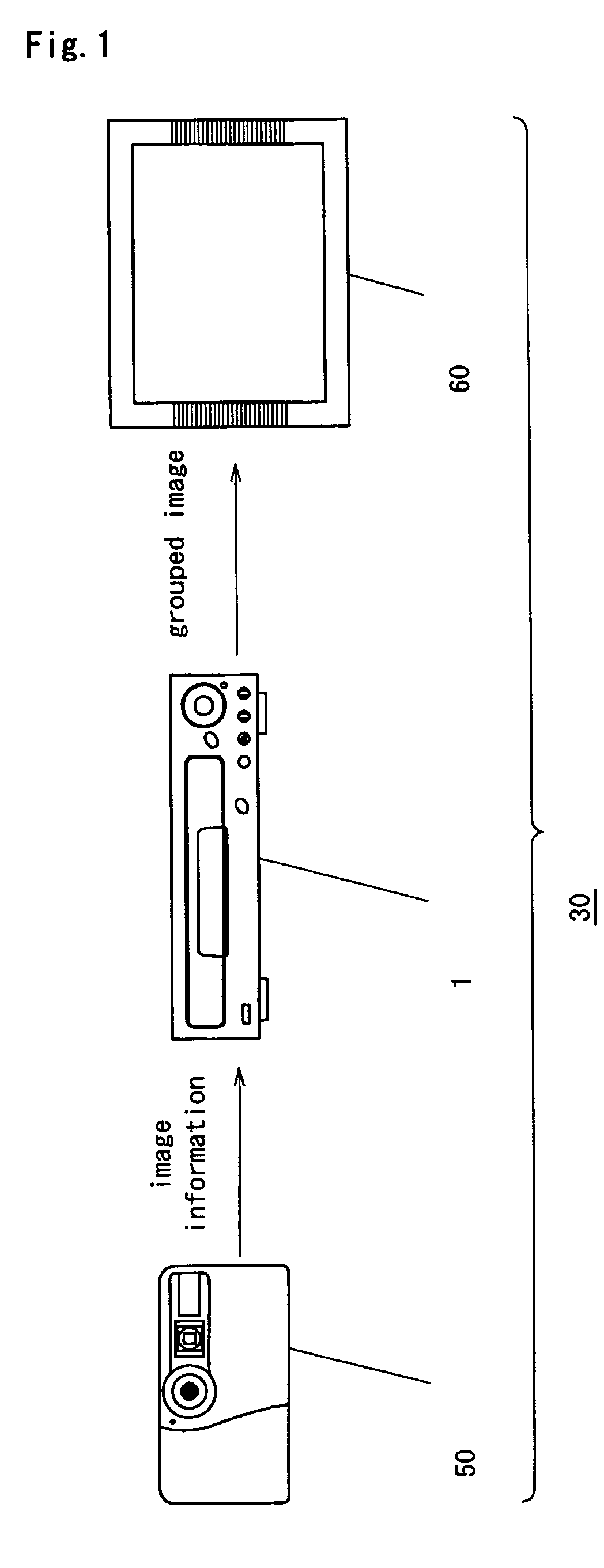
[0073]FIG. 1 is a diagram showing the image-classifying system in the first embodiment of the present invention. As shown in FIG. 1, an image-classifying system 30 in the embodiment of the present invention comprises: a shooting apparatus 50 (e.g. as a digital camera and a movie camera that shoots images); an image-classifying apparatus 1 that classifies an image (a still image or a moving image) shot by the shooting apparatus 50; and a display apparatus 60, which displays the image that is classified by the image-classifying apparatus 1.

[0074] The image-classifying apparatus 1 can classify the image information for each event by sending image information to the image-classifying apparatus 1...

second embodiment

[0107] Next, an image-classifying apparatus, an image-classifying method, and a program in a second embodiment of the present invention are explained.

[0108]FIG. 6 is a block diagram of an image-classifying apparatus 21 in the second embodiment of the present invention.

[0109] As shown in FIG. 6, when comparing between the image-classifying apparatus 21 in the second embodiment of the present invention and the image-classifying apparatus 1 of the first embodiment of the present invention, the difference point is that the image-classifying apparatus 21 in the second embodiment of the present invention comprises: an image storing unit 12 that stores the image information sent from the shooting apparatus 50; a time information-extracting unit 13 that extracts the time information from the shooting information of the image information; and a time difference-calculating unit 14 that calculates the difference between the time when an image was shot and the time when another image was shot...

third embodiment

[0174] An image-classifying apparatus 31 of a third embodiment of the present invention is described. FIG. 12 is a block diagram of the image-classifying apparatus 31 according to the third embodiment of the present invention.

[0175] As illustrated in FIG. 12, points different between the image-classifying apparatus 21 according to the second embodiment of the present invention and the image-classifying apparatus 31 according to the third embodiment of the present invention are as follows. The image-classifying apparatus 31 does not comprise: the time information-extracting unit 13; and the time difference-calculating unit 14. However, the image-classifying apparatus 31 comprises: the distance difference-calculating unit 32 that calculates a distance difference based on position information extracted by the position information-extracting unit 2.

[0176] According to the points mentioned above, the image information-classifying unit 34 inputs a value of the reference distance outputt...


PUM


Abstract

An image information-inputting unit inputs image information including position information indicating a position where an image was shot. A reference distance-calculating unit calculates a reference distance from a predetermined reference position utilizing the image information. An image information-classifying unit classifies the image information based on the reference distance.

Description

BACKGROUND OF THE INVENTION [0001] 1. Field of the Invention [0002] The present invention relates to an image-classifying apparatus, an image-classifying method, and a program operable to classify image information of a still image or a moving image shot by a shooting apparatus, for example, a digital still camera, a camera-built-in cellular phone, a movie camera, and so on. [0003] 2. Description of the Related Art [0004] In recent years, a personal shooting apparatus, which shoots digital images, for example, a digital still camera (hereinafter, a digital camera) and a camera-built-in cellular phone, has spread rapidly. Since storage capacity of the shooting apparatus increases, a user thereof can take many images. However, the user cannot see all images within a limited time in many cases. A technique that the user can see more efficiently the images is needed. [0005] In order to solve this subject, Japanese patent application Laid-open No. 2003-58867 discloses a method, comprisin...

Claims


Application Information

Patent Timeline
IPC IPC(8): G06F17/30G06T1/00H04N1/32H04N5/225H04N5/77H04N9/804H04N9/82
CPCG06F17/30265G06F17/3028H04N1/32128H04N5/45H04N5/772H04N2201/3253H04N9/8047H04N9/8205H04N2201/3214H04N2201/3215H04N2201/3247H04N9/8042G06F16/51G06F16/58
Inventor HAMASAKI, SHOGOSASO, ATSUSHISUGIMOTO, NORIKOFUJIOKA, SOICHIRO
Owner SOVEREIGN PEAK VENTURES LLC
Why Eureka
Try Eureka