Method and apparatus for automotive rim edge analysis and corrective weight selection guide

a technology of corrective weight selection and rim edge analysis, which is applied in vehicle tyre testing, vehicles, instruments, etc., can solve the problems that no wheel balancing system discloses or suggests a method and apparatus

Active Publication Date: 2005-06-23
SNAP ON INC
View PDF10 Cites 23 Cited by
  • Summary
  • Abstract
  • Description
  • Claims
  • Application Information

AI Technical Summary

Problems solved by technology

None of these previous and existing wheel balancing systems disclose or suggest a method and apparatus for automatically d

Method used


Image

  • Method and apparatus for automotive rim edge analysis and corrective weight selection guide
  • Method and apparatus for automotive rim edge analysis and corrective weight selection guide
  • Method and apparatus for automotive rim edge analysis and corrective weight selection guide

Examples


Embodiment Construction

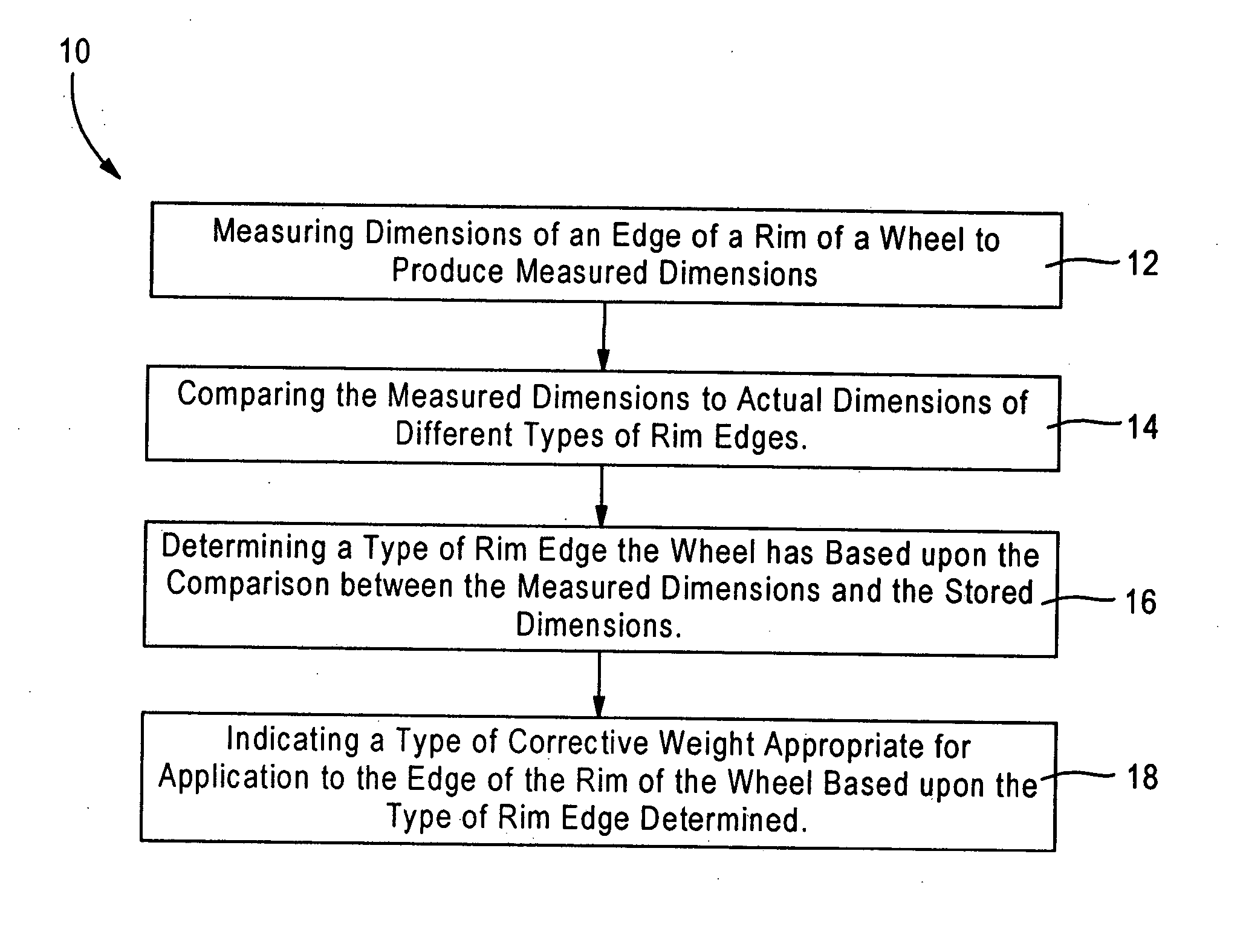
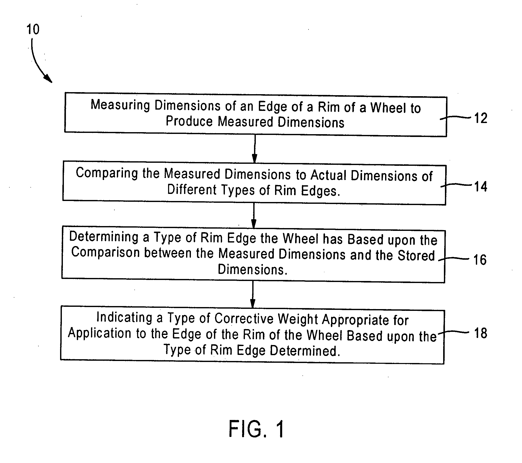
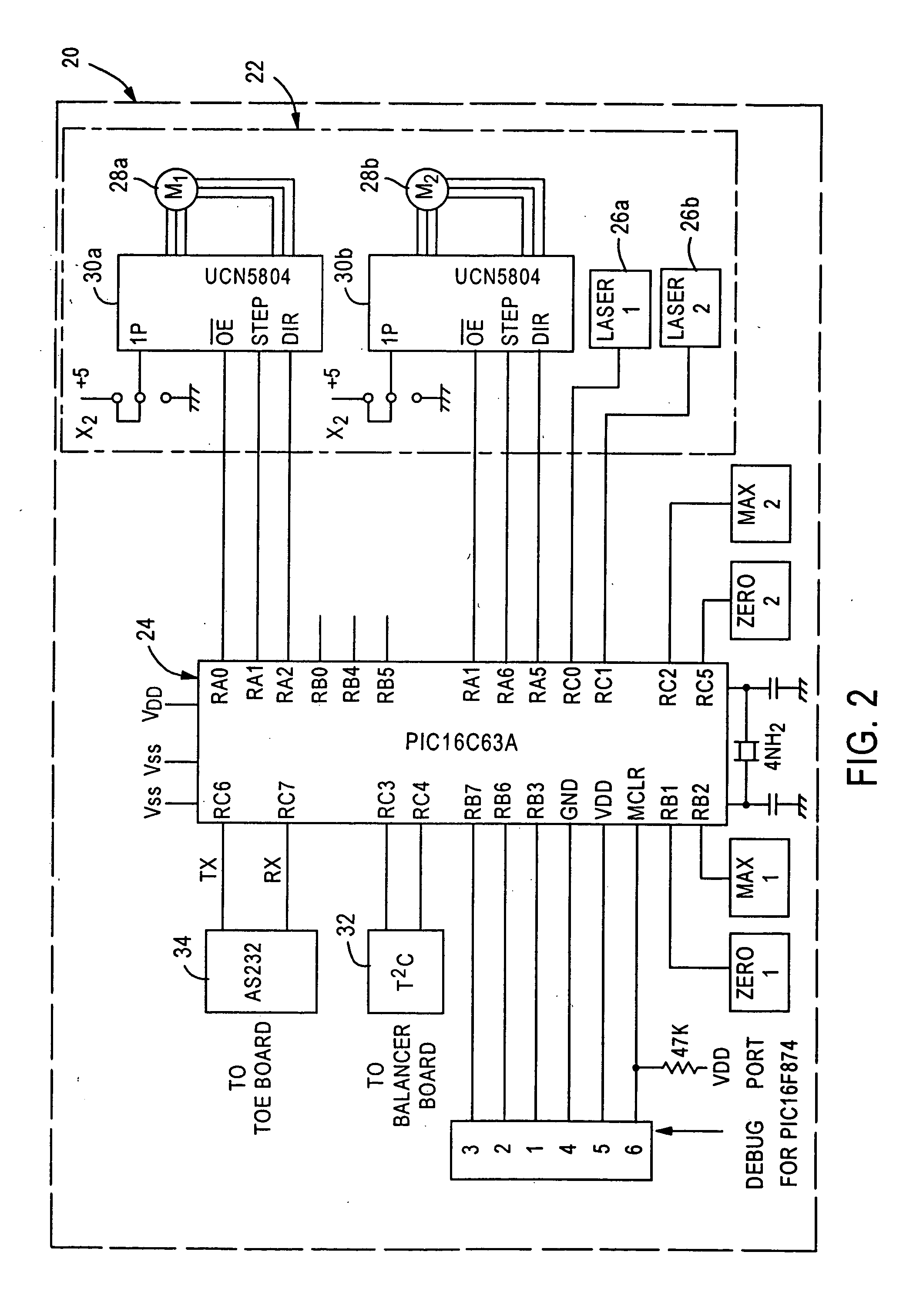
[0025] Referring to FIGS. 1 and 2, the present disclosure is directed to a method 10 and an apparatus 20 for automatically analyzing a rim edge of a wheel and suggesting a proper type of clip-on corrective weight to be secured to the rim edge. The method 10 and the apparatus 20 of the present disclosure can be used with, or incorporated into, motor vehicle wheel balancing systems and used to suggest the proper type of clip-on corrective weight once a proper amount of the weight has been determined by the balancing system. Before discussing the method 10 and the apparatus 20 of FIGS. 1 and 2, an exemplary embodiment of a balancing machine 100 according to the prior art will first be discussed to provide background information.

[0026] Referring to FIG. 22, an exemplary embodiment of a balancing machine 100 according to the prior art and, which may be utilized with the apparatus and the method of the present disclosure, is shown. The balancing machine 100 includes a base 102 supporting...


PUM


Abstract

A method of determining a type of corrective weight for application to an edge of a rim of a wheel for correcting imbalance of the wheel, including measuring dimensions of an edge of a rim of a wheel to produce measured dimensions, comparing the measured dimensions to actual dimensions of different types of rim edges, determining a type of rim edge the wheel has based upon the comparison between the measured dimensions and the stored dimensions, and indicating a type of corrective weight appropriate for application to the edge of the rim of the wheel based upon the type of rim edge determined.

Description

FIELD OF THE DISCLOSURE [0001] The present disclosure is directed to motor vehicle wheel balancing systems, and more particularly to a method and an apparatus for use with such systems for automatically analyzing a rim edge of a wheel and suggesting the proper type of clip-on corrective weight to be secured to the rim edge. DESCRIPTION OF THE RELATED ART [0002] It is well known in the automotive wheel balancing art that to compensate for a combination of static imbalance (where the heaviest part of the wheel will seek a position directly below the mounting shaft) and couple imbalance (where the rotating wheel causes torsional vibrations on the mounting shaft), at least two correction weights are required which are separated axially along the wheel surface, coincident with weight location “planes”. For clip-on weights the “left plane” comprises the left (innermost) rim lip or edge circumference while the “right plane” comprises the right rim edge. For adhesive weights, the planes can...

Claims


Application Information

Patent Timeline
IPC IPC(8): G01M1/02G01M1/08G01M1/32
CPCG01M1/02G01M1/326G01M1/08
Inventor CULLUM, WILLIAM DAVIDZHOU, WEN-YUROGERS, FREDERICK J.
Owner SNAP ON INC
Why Eureka
Try Eureka