Fuel injector with an armature assembly having a continuous elongated armature and a metering assembly having a seat and polymeric support member

Inactive Publication Date: 2005-06-23
CONTINENTAL AUTOMOTIVE SYST INC
View PDF27 Cites 6 Cited by
  • Summary
  • Abstract
  • Description
  • Claims
  • Application Information

AI Technical Summary

Benefits of technology

[0008] The present invention provides for, in one aspect, a fuel injector that is believed to reduce or eliminate these drawbacks of the known fuel injectors while maintaining substantially the same operative perf

Problems solved by technology

While the known fuel injectors are suited to the task of metering fuel, it is believed that the known fuel injectors may have certain assembly or component drawbacks that require extensive manufacturing process to be undertaken to ensure that the injector are suitable for commercial applications.
Others include the potential manufacturing di

Method used


Image

  • Fuel injector with an armature assembly having a continuous elongated armature and a metering assembly having a seat and polymeric support member
  • Fuel injector with an armature assembly having a continuous elongated armature and a metering assembly having a seat and polymeric support member
  • Fuel injector with an armature assembly having a continuous elongated armature and a metering assembly having a seat and polymeric support member

Examples


Embodiment Construction

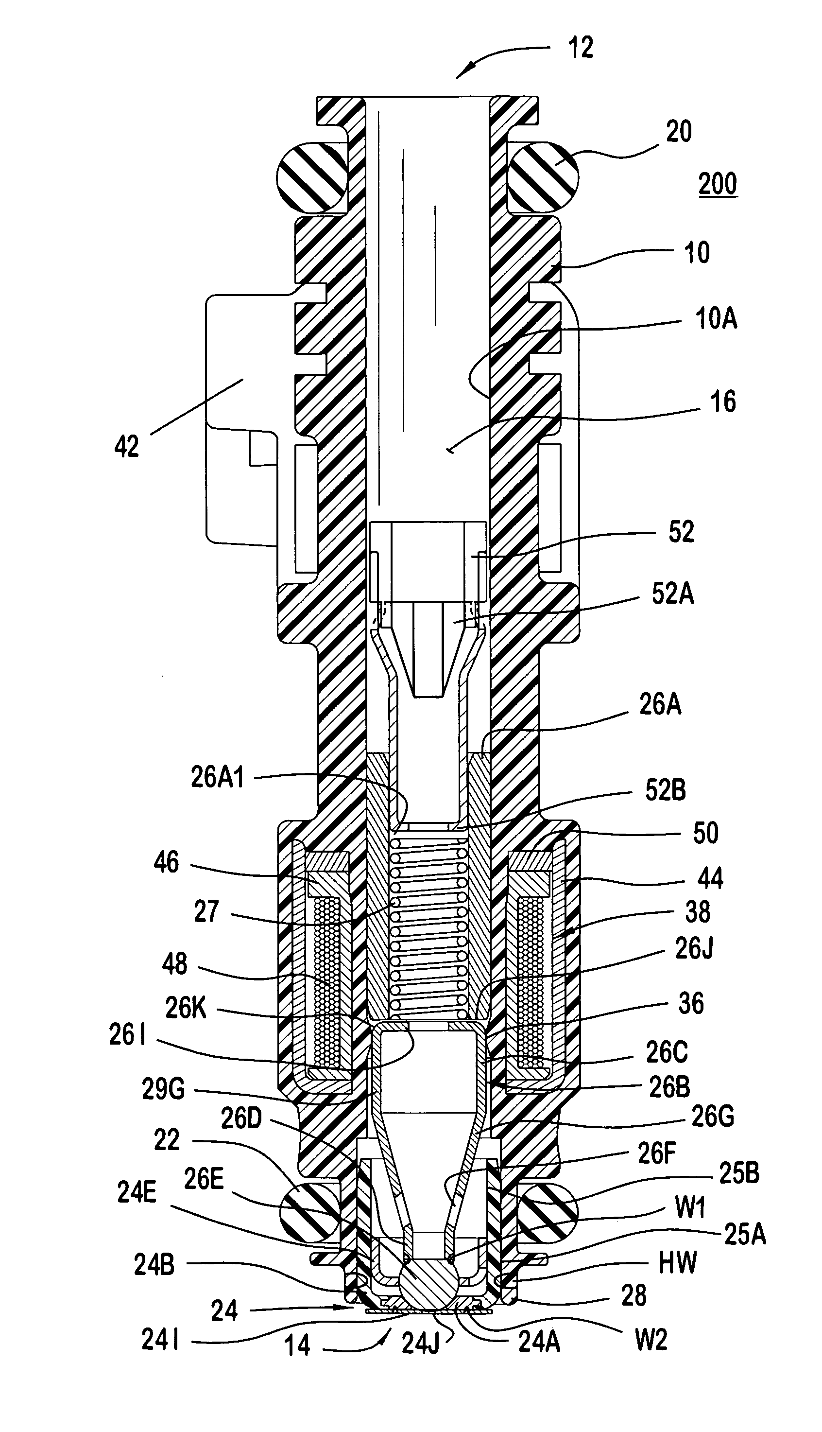
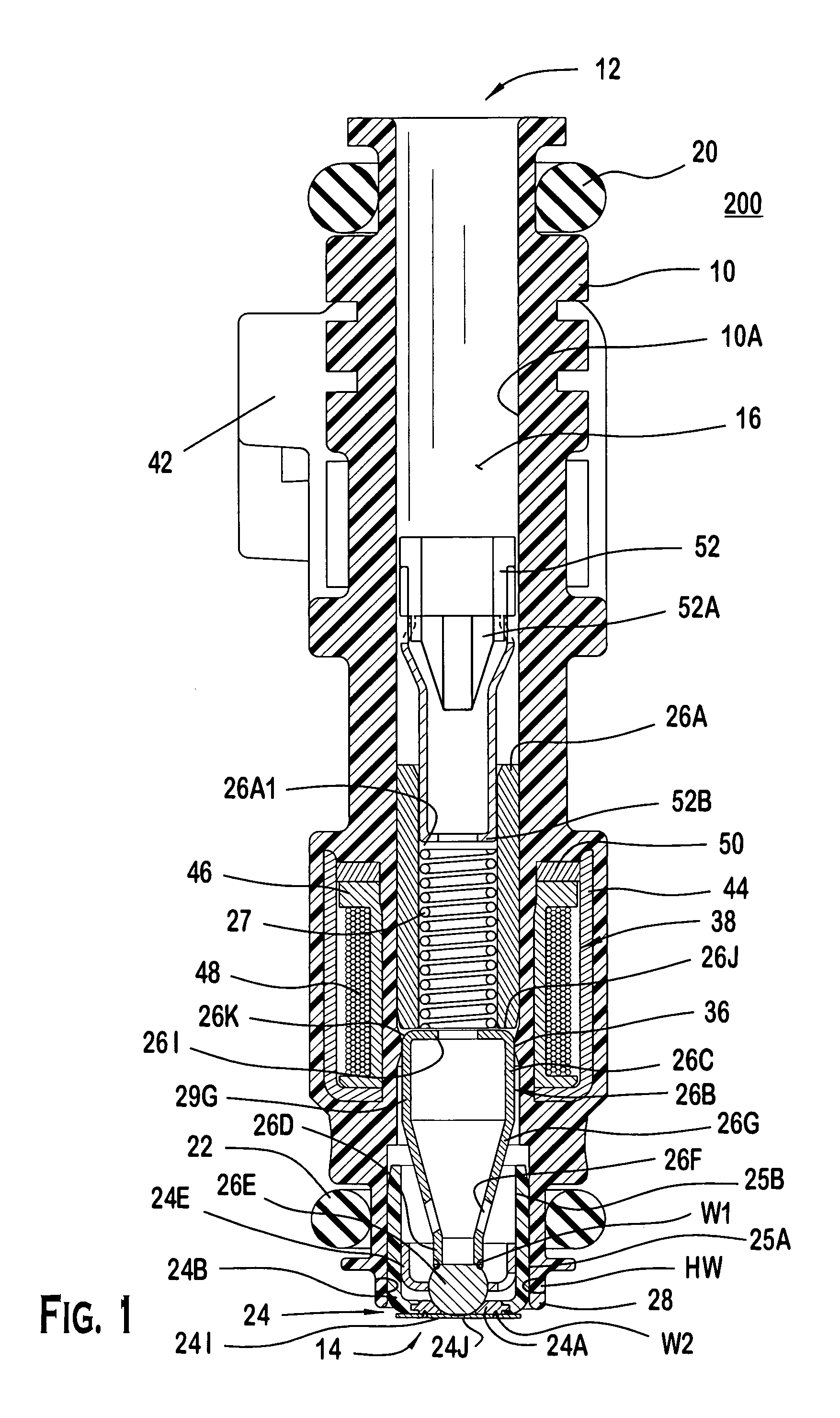
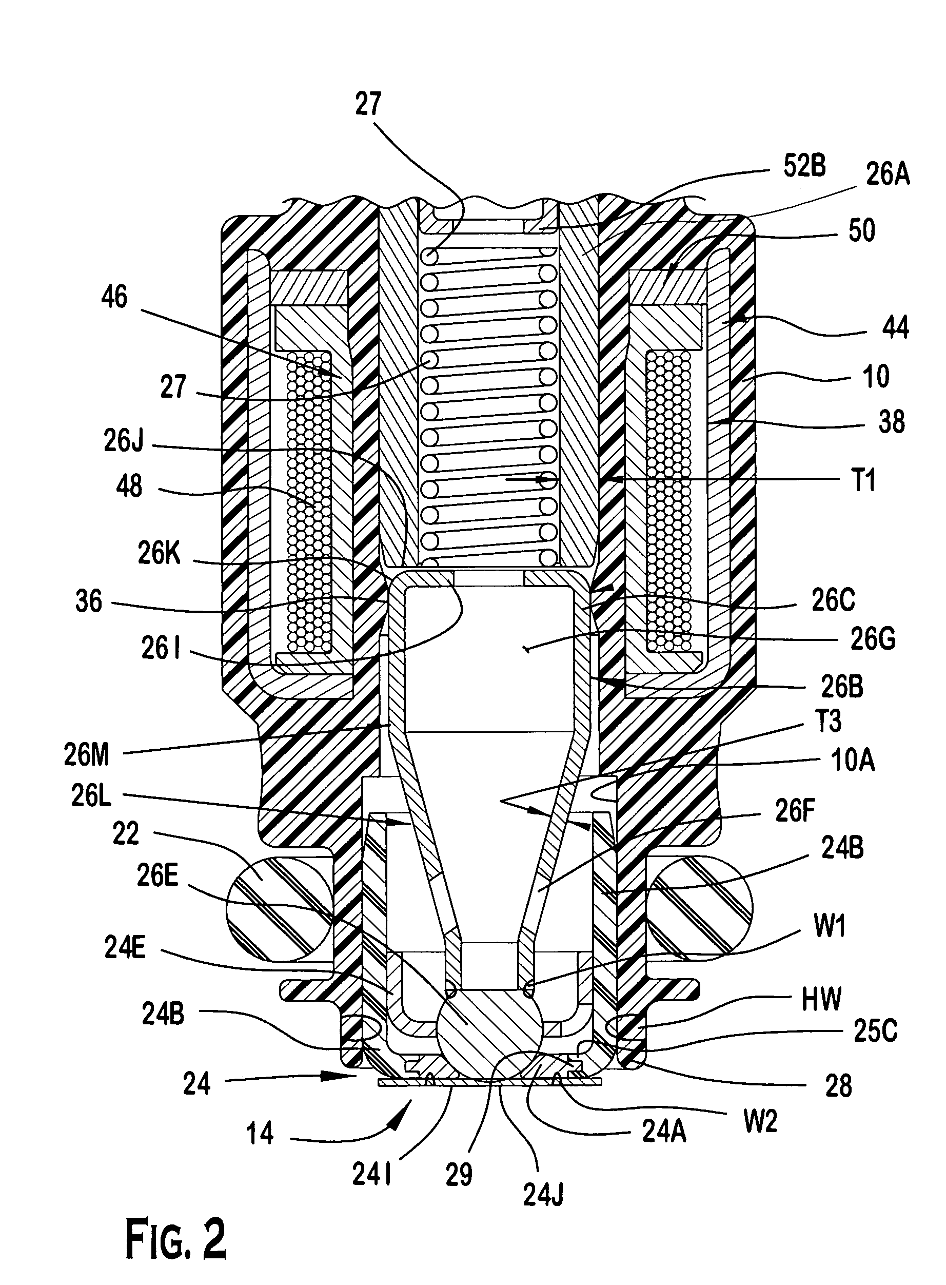
[0016]FIGS. 1-3 illustrate the preferred embodiments of a fuel injector 100. Referring to FIGS. 1 and 2, the fuel injector 100 includes a continuous polymeric housing 10 extending from an inlet 12 to an outlet 14 along a longitudinal axis A-A. The polymeric housing 10 includes a polymeric wall surface or bore 10A that directly faces the longitudinal axis A-A to define a first passage 16 in which fuel can flow from the inlet 12. The first passage 16 extends from the inlet 12 to communicate with a second passage 18 formed by a plurality of internally mounted components. The first passage 16 includes the polymeric bore 10A that extends from a first external seal 20 proximate the inlet 12 to a second external seal 22 proximate an outlet 14 along the longitudinal axis A-A. Disposed within a portion of the polymeric bore 10A is a metering assembly 24 proximate the second external seal 22. A closure assembly 26 is disposed proximate the metering assembly 24, which is coupled to a rim porti...


PUM

PropertyMeasurementUnit
Thicknessaaaaaaaaaa
Massaaaaaaaaaa
Thicknessaaaaaaaaaa

Abstract

A fuel injector is described that includes a polymeric housing, pole piece, filter assembly, coil assembly, spring member, armature assembly and metering assembly. The polymeric housing has a passageway extending between an inlet and an outlet along a longitudinal axis. The pole piece is disposed in the passageway. The metering assembly is secured to the polymeric housing proximate the outlet. The metering assembly has a seat molded to a polymeric support member. The polymeric support member may be cylindrical and bonded to the polymeric bore proximate the outlet. A method of operating the fuel injector is described.

Description

PRIORITY [0001] This application claims the benefits under 35 U.S.C. § 119 based on Provisional Application Ser. No. 60 / 531,206, entitled “Plastic Bodied Fuel Injector,” (Attorney Docket No. 2003P19370US), and filed on Dec. 19, 2003, which application is incorporated herein in its entirety into this application.BACKGROUND OF THE INVENTION [0002] Examples of known fuel injection systems use an injector to dispense a quantity of fuel that is to be combusted in an internal combustion engine. The quantity of fuel that is dispensed is varied in accordance with a number of engine parameters such as engine speed, engine load, engine emissions, etc. [0003] Known electronic fuel injection systems monitor at least one of the engine parameters and electrically operate the injector to dispense the fuel. It is believed that examples of known injectors use electromagnetic coils, piezoelectric elements, or magnetostrictive materials to actuate a valve. [0004] A known fuel injector utilizes a pleth...

Claims


Application Information

Patent Timeline
IPC IPC(8): B05B1/30B29C45/14F02M39/00F02M43/00F02M51/00F02M51/06F02M55/00F02M59/00F02M61/00F02M61/12F02M61/16F02M61/18F02M63/00
CPCF02M51/005F02M51/0625F02M51/0664F02M51/0667F02M51/0682F02M61/12F02M2200/9015F02M61/166F02M61/168F02M61/18F02M61/1853F02M61/188F02M2200/8061F02M61/165B29C65/1609B29C65/1616B29C65/1635B29C65/1654B29C65/1677B29C65/1683B29C65/565B29C65/72B29C66/12441B29C66/12469B29C66/5344B29C66/65B29C66/71B29C66/7212B29C66/73921B29C66/919B29K2023/00B29K2077/00B29K2033/12B29K2023/12B29K2027/16B29K2067/006B29K2309/08
Inventor HORNBY, MICHAEL J.
Owner CONTINENTAL AUTOMOTIVE SYST INC
Why Eureka
Try Eureka