Apparatus for detecting a distance and apparatus for detecting a body

a technology of detecting distance and apparatus, applied in the direction of amplitude demodulation, pulse technique, instruments, etc., can solve the problem of not being able to favorably compress the pulse width of the received signal for the received signal reflected by a body that is uniformly moving, and the noise components of the frequency components that pass through the band-pass filter are difficult to remove, etc. problem, to achieve the effect of improving the sn (signal to noise) ratio of the received signal

Active Publication Date: 2005-06-23
DENSO CORP +1
View PDF15 Cites 27 Cited by
  • Summary
  • Abstract
  • Description
  • Claims
  • Application Information

AI Technical Summary

Benefits of technology

[0007] This invention was accomplished in view of the above problems, and its object is to provide an apparatus for detecting a distance and an apparatus for detecting a body, which are capable of improving the SN (signal to noise) ratio of the received signals.

Problems solved by technology

In the above conventional ultrasonic distance measuring apparatus, the frequency components of transmission signals are obtained through the band-pass filter, making it difficult to remove noise components in the frequency components that pass through the band-pass filter.
According to the above pulse compression method, further, improvement in the SN ratio can be expected to some extent for the static body (which is not moving) but the pulse cannot be favorably compressed for the received signals reflected by a body that is uniformly moving.
When the pulses are compressed, therefore, no correlation is maintained relative to the modulated signals and, as a result, the pulse widths of the received signals are not compressed as desired.

Method used


Image

  • Apparatus for detecting a distance and apparatus for detecting a body
  • Apparatus for detecting a distance and apparatus for detecting a body
  • Apparatus for detecting a distance and apparatus for detecting a body

Examples


first embodiment

(First Embodiment)

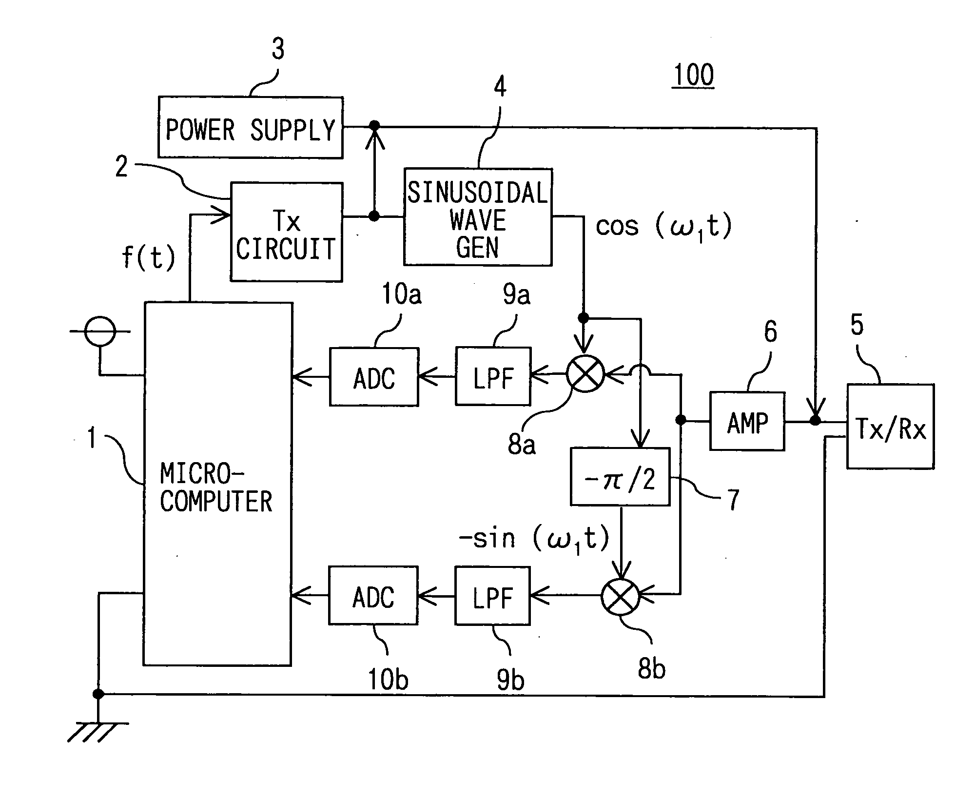
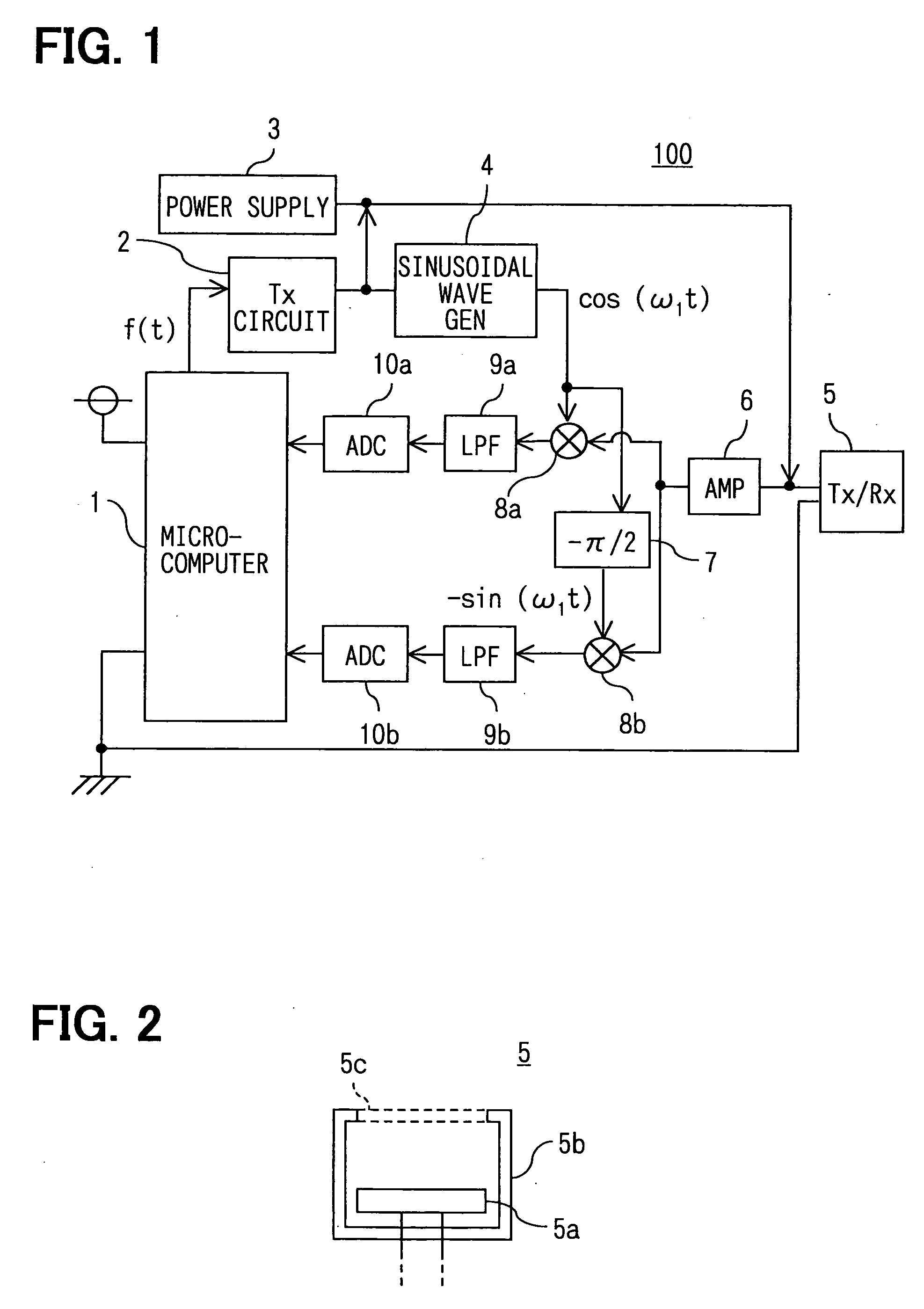
[0172]FIG. 1 is a diagram illustrating the constitution of an apparatus for detecting a distance according to this embodiment. As shown, an apparatus 100 for detecting a distance of the embodiment is constituted by a microcomputer 1, a transmitter circuit 2 (shown as Tx CIR), a power supply device 3, a sinusoidal wave generator 4, a transmitter / receiver microphone 5 (Tx / Rx MIC), an amplifier 6 (AMP), a phase shifter 7, multipliers 8a and 8b, LPFs (low-pass filters) 9a and 9b, and analog / digital converters 10a and 10b (ADCs).

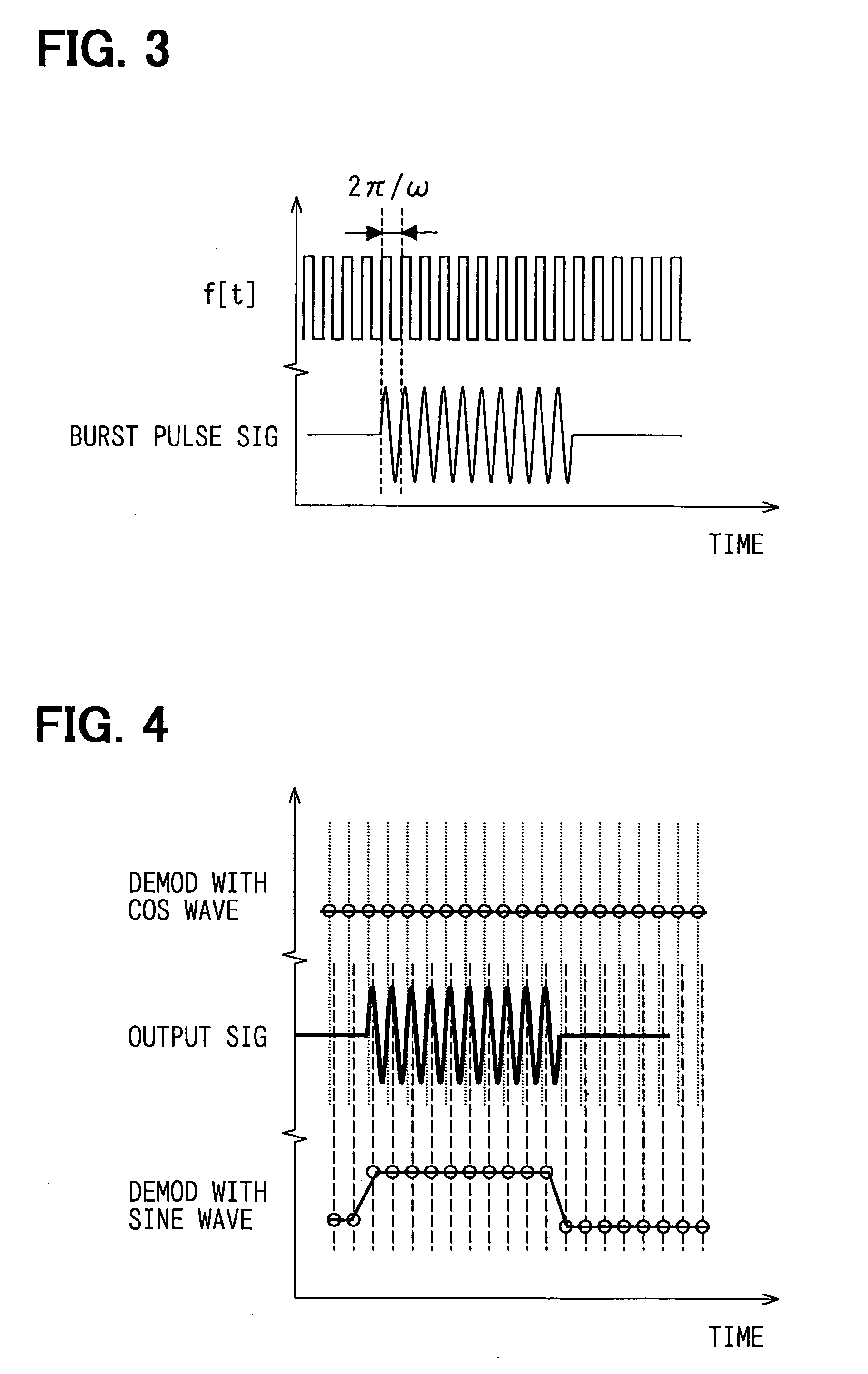
[0173] The microcomputer 1 may be a conventional microcomputer constituted by a ROM, a RAM, a CPU, an I / O and a bus for connecting them (not shown for ease of illustration). Referring to FIG. 3, the microcomputer 1 forms pulse signals f[t] having an angular frequency (ω) and sends them to the transmitter circuit 2. The microcomputer 1, further, receives output signals from the ADCs 10a and 10b, and executes a predetermined signal processing for...

modified example 1

[0196] In the embodiment, the orthogonal demodulation is effected by using sine wave signals of an angular frequency in synchronism with the angular frequency (ω) of the burst pulse signals. Here, however, the angular frequency of the sine wave signals used for the orthogonal demodulation may be selected to be equal to the resonance angular frequency of the transmitter / receiver microphone 5.

[0197] Namely, in general, the pulse signals f[t] for driving the transmitter / receiver microphone 5 are set in advance to be in agreement with the resonance frequency of the piezoelectric element 5a, so that the piezoelectric element 5a efficiently receives the reflected waves. By orthogonally demodulating the reflected wave signals by using the sine wave signals of a frequency nearly equal to the resonance frequency of the piezoelectric element 5a, therefore, the action and effect same as those of this embodiment can be expected.

modified example 2

[0198] When, for example, a body reflecting the transmission waves is in motion, a frequency component of an angular frequency (ω2) is added to the reflected waves received by the transmitter / receiver microphone 5 because of the Doppler effect. The reflected waves affected by the Doppler effect are orthogonally demodulated, and the demodulated signals are passed through the LPF to be added with a term ejω2t relative to the above formula 27 and to be added with a rotational vector ejω2 on the IQ plane as expressed by the following formula (28),

LPF output=A×f[t]×ejθ×ejω2t  (28)

[0199] When the reflecting body is in uniform motion, however, the angular frequency (ω2) assumes a constant value, and the above formula (28) can be rewritten as the following formula (29),

LPF output=A×f[t]×ejθ×ejω2t=A×f[t]×ejθ×ejθ(t)  (29)

[0200] Here, a difference between the output signal produced last time by the LPF and the output produced this time can be expressed by the following formula (30),

Difference ...


PUM


Abstract

In an apparatus for detecting a distance and improving the SN ratio of received signals, an angular frequency (ω1) of sinusoidal wave signals generated by a sinusoidal wave generator is brought into synchronism with an angular frequency (ω) of burst pulse signals, and signals received by a transmitter / receiver microphone are orthogonally demodulated by using sinusoidal wave signals of the synchronized angular frequency. A microcomputer adds up the vectors of the demodulated signals for only a period of time equal to a section of transmitting the transmission waves from the transmitter / receiver microphone. A distance to a body is detected by using the received signals of which the vectors are added up.

Description

CROSS REFERENCE TO RELATED APPLICATIONS [0001] This application is based upon, claims the benefit of priority of, and incorporates by reference the contents of, Japanese Patent Application No. 2003-420010 filed on Dec. 17, 2003, Japanese Patent Application No. 2004-31244 filed on Feb. 6, 2004, and Japanese Patent Application No. 2004-178739 filed on Jun. 16, 2004. FIELD OF THE INVENTION [0002] This invention relates to an apparatus for detecting a distance and an apparatus for detecting a body. BACKGROUND OF THE INVENTION [0003] There has heretofore been proposed an ultrasonic distance measuring apparatus for measuring a distance to a reflecting body by transmitting ultrasonic waves and receiving reflected waves thereof. According to this ultrasonic distance measuring apparatus, the received signals are passed through a band-pass filter to obtain frequency components only of the transmitted signals, and the obtained signals are detected for their envelope to detect the rising portio...

Claims


Application Information

Patent Timeline
Patent Type & Authority Applications(United States)
IPC IPC(8): G01S7/28G01S7/527G01S15/00G01S15/08G01S15/10G01S15/42
CPCG01S15/104G01S7/5273
Inventor KATOU, KOUJITAKEICHI, MASAKAZUSATO, YOSHIHISAHATTORI, TOSHIHIRO
Owner DENSO CORP
Why Eureka
Try Eureka