
Linear compressor

a compressor and linear technology, applied in the direction of positive displacement liquid engines, pump components, piston pumps, etc., can solve the problem of inability to use compressors, and achieve the effect of radically reducing the stiffness of the gas pressure in the compressing chamber

Inactive Publication Date: 2005-06-23
SAMSUNG ELECTRONICS CO LTD
View PDF6 Cites 58 Cited by
  • Summary
  • Abstract
  • Description
  • Claims
  • Application Information

AI Technical Summary

Benefits of technology

[0020] Accordingly, it is an aspect of the present invention to provide a linear compressor usable also in a large displacement section in which a stiffness of a gas pressure in a compressing chamber is radically decreased.

Problems solved by technology

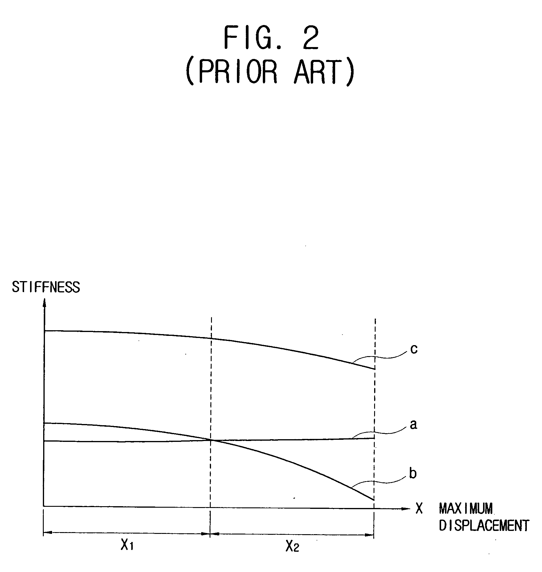
Accordingly, the conventional linear compressor can be used only in the small displacement section X1 in which the addition c of the stiffness a of the conventional spring and the average stiffness b of the gas pressure remains fairly constant and approximately the same as the frequency of the electric power, thereby causing a problem in that the conventional linear compressor cannot be used in the large displacement section X2 in which the average stiffness of the gas pressure is radically changed with a highly nonlinear property.

Method used


Image

  • Linear compressor
  • Linear compressor
  • Linear compressor

Examples


Embodiment Construction

[0038] Reference will now be made in detail to illustrative, non-limiting embodiments of the present invention, examples of which are illustrated in the accompanying drawings, wherein like reference numerals refer to like elements throughout. The exemplary embodiments are described below in order to explain the present invention by referring to the figures.

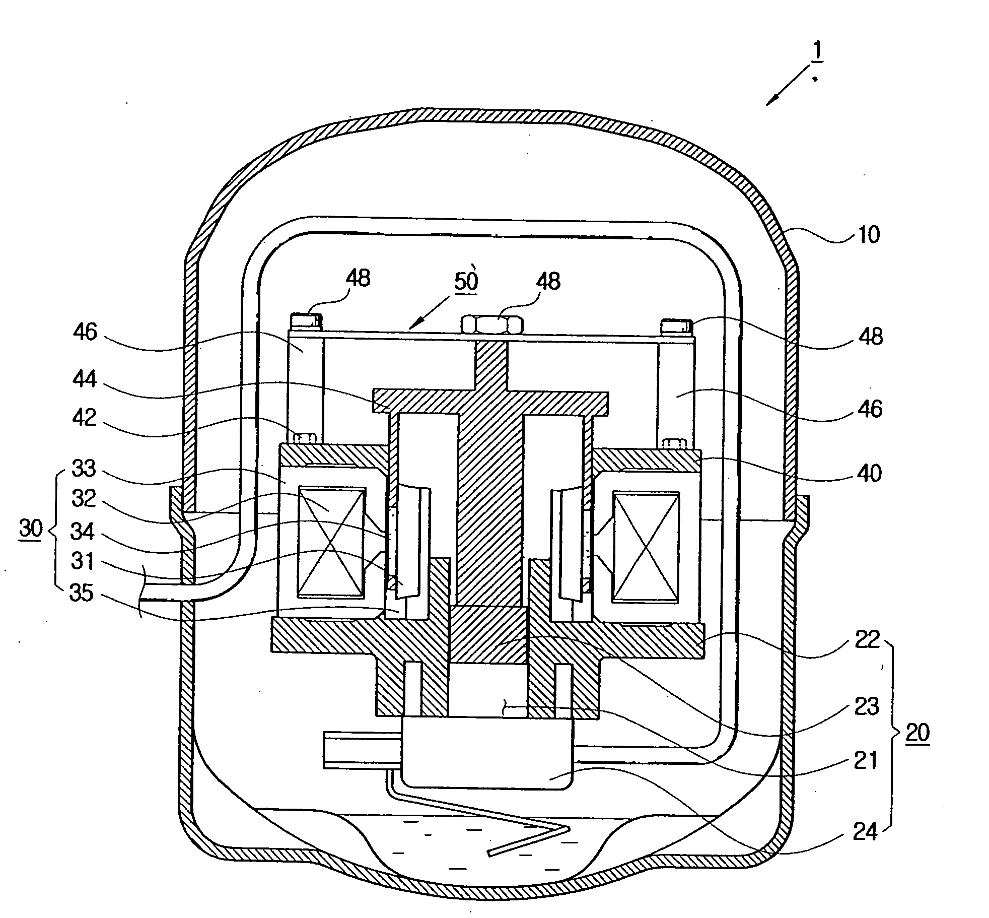
[0039] As shown in FIG. 3, a linear compressor 1 according to an embodiment of the present invention comprises a sealed outer casing 10, a compressing part 20 for sucking refrigerant gas to compress and discharge the refrigerant gas and a driver 30 to operate the compressing part 20.

[0040] The compressing part 20 comprises a cylinder block 22 to support a bottom of an outer core 33 (to be described later) of the driver 20 and to form a compressing chamber 21, a piston 23 reciprocatably provided in the compressing chamber 21 and a cylinder head 24 provided under the cylinder block 22 and comprising a sucking valve (not shown) and...


PUM


Abstract

A linear compressor includes: a cylinder block forming a compressing chamber; a piston reciprocatably provided in the compressing chamber; a reciprocating member connected to the piston to reciprocate with the piston as a single body; a driver driving the reciprocating member to reciprocate; and a resonance spring including a first connecting part formed with a plurality of first connecting holes to permit connection to the cylinder block, and a second connecting part that is provided inside of the first connecting part and formed with a second connecting hole to permit connection to the reciprocating member to reciprocate with the reciprocating member. A plurality of arms spaced apart from one another are disposed between the first connecting part and the second connecting part, each of the arms including a first end connected to the first connecting part to be positioned between the plurality of first connecting holes.

Description

CROSS-REFERENCE TO RELATED APPLICATIONS [0001] This application claims the benefit of Korean Patent Application No. 2003-092796, filed on Dec. 18, 2003, in the Korean Intellectual Property Office, the disclosure of which is incorporated herein by reference. BACKGROUND OF THE INVENTION [0002] 1. Field of the Invention [0003] An apparatus consistent with the present invention relates to a linear compressor and, more particularly, to a linear compressor having a resonance spring of an improved structure. [0004] 2. Description of the Related Art [0005] Generally, different from a reciprocating compressor, a linear compressor is of a free-piston structure having no connecting rod to restrict movement of a piston. The linear compressor comprises an outer casing to seal a predetermined space, a compressing part accommodated in the outer casing to suck and compress / discharge refrigerant gas and a driver to operate the compressing part by electric power from the outside. [0006] The compressi...

Claims


Application Information

Patent Timeline
IPC IPC(8): F04B17/04F04B35/04
CPCF04B35/045F04B17/04
Inventor KANG, JEONG-HOONJOO, JAE-MAN
Owner SAMSUNG ELECTRONICS CO LTD
Learn More