
Box-erecting machine

Inactive Publication Date: 2005-06-23
MCALPINE GILROY CLEMENTS +1
View PDF0 Cites 29 Cited by
  • Summary
  • Abstract
  • Description
  • Claims
  • Application Information

AI Technical Summary

Benefits of technology

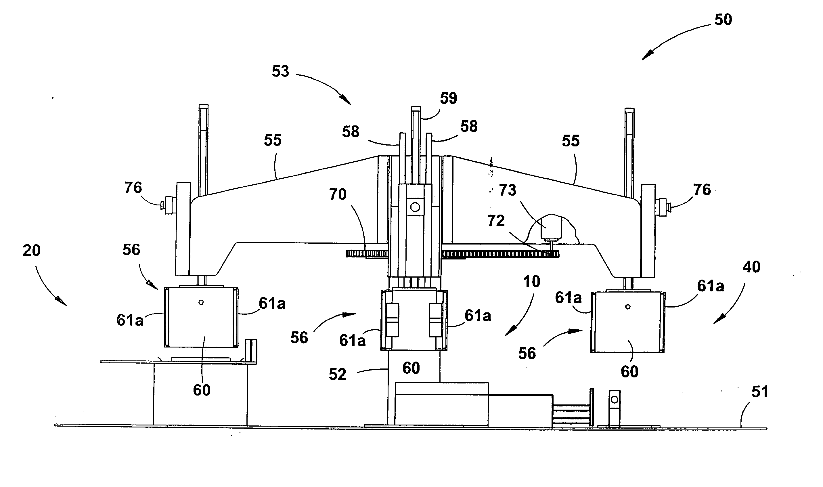
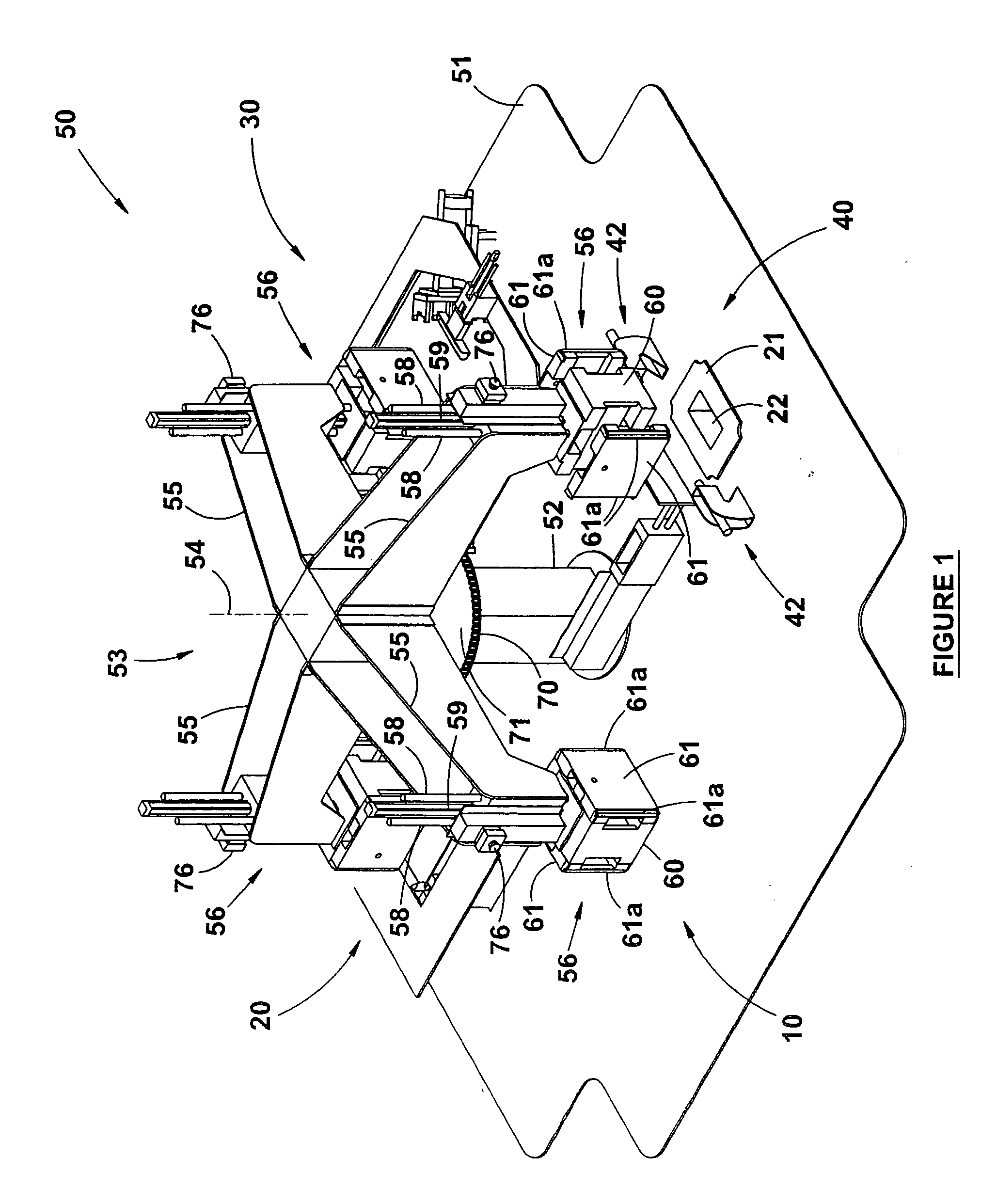
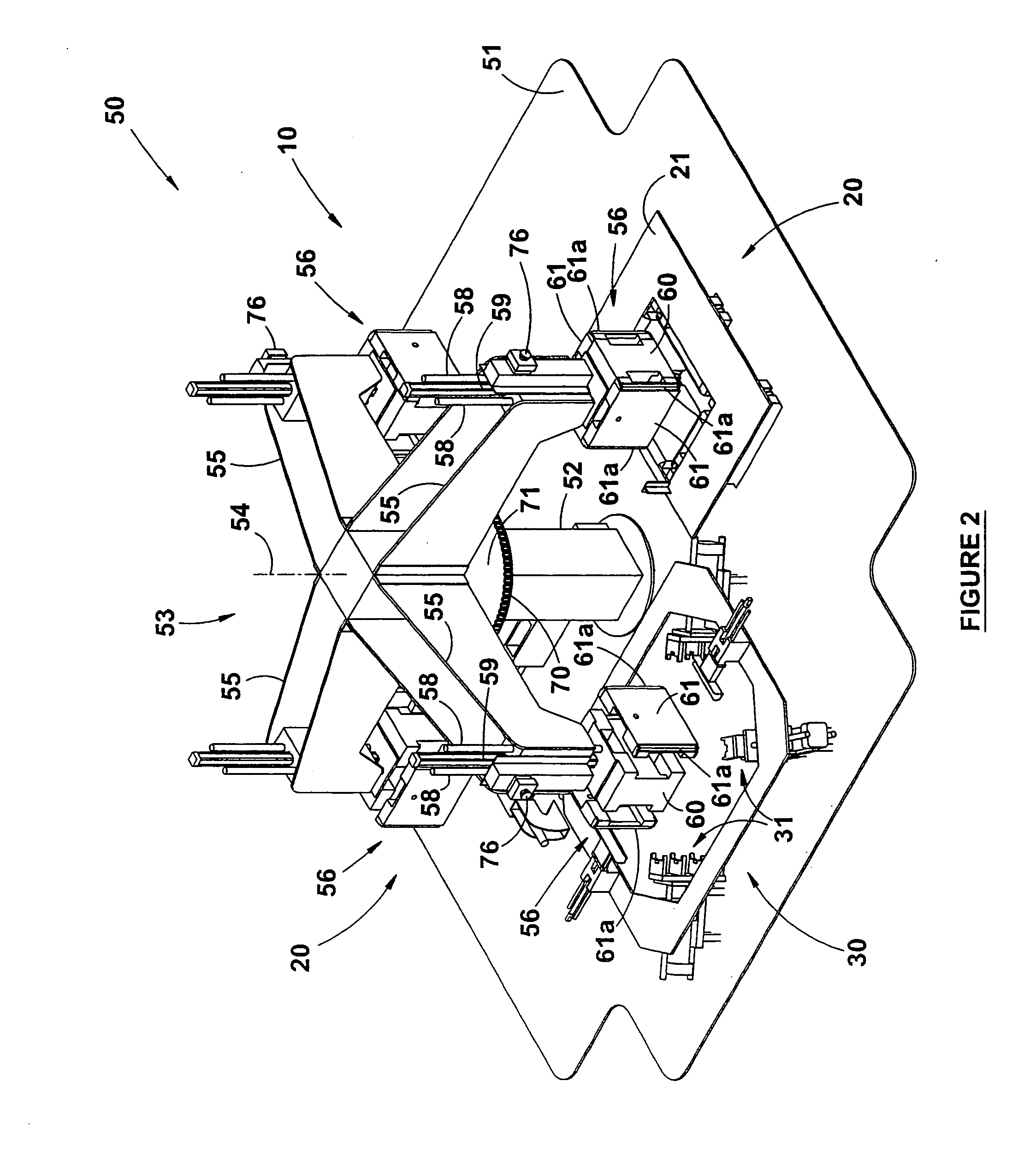
[0045] At the same time that the mandrel 56 is displaced downwardly into the blank-folding cavity, pneumatic suction is applied through ports 26 in the cheek plates 61 of the mandrel 56 to facilitate the retention of the now folded blank on the mandrel. The last step at station 20 is withdrawal of the mandrel by means of the piston and cylinder assembly 59 to the former position

Problems solved by technology

This has proved to be laborious and time consuming and, indeed, the applicant believes that such manual erection of boxes will not meet the r

Method used


Image

  • Box-erecting machine
  • Box-erecting machine
  • Box-erecting machine

Examples


Example

[0032] Referring firstly to FIGS. 11-13 of the accompanying drawings, there is shown a rectangular box 80 and its constituent parts. Typically, the box has a base 81, opposed side walls 82, opposed end walls 83 and a pair of openable lids 84, all made from a single blank of sheet material such as polyethylene. The box is held together by four upright corner posts 85, each of which comprises an inner part 86 and an outer part 87. The inner and outer parts 86, 87 are held together by a snap fit in which lugs 88 on the inner part are snap fitted into apertures 89 in the outer part 87. When the inner and outer parts 86, 87 are thus engaged, they trap and hold the ends of the side walls and end walls 82, 83 respectively at each corner of the box 80. As will be most evident from FIG. 12.2, the lugs 88 of the inner part 86 of a post 85 are accommodated in apertures 90 in the side walls and end walls 82, 83 of the box, which apertures are provided along the height of the walls at positions ...


PUM


Abstract

A box-erecting machine comprising a support structure and a rotatable head mounted on the support structure for rotation about an axis, the rotatable head carrying a plurality of four-cornered mandrels, means for displacing each mandrel away from and towards the rotatable head, and means for rotating the rotatable head in discrete steps so as to locate each mandrel at consecutive erecting stations of the machine and thereby to permit progressive erection of a rectangular box through the erecting stations from a blank of sheet-like material with corner posts located and connected in each of the four corners of the box.

Description

FIELD OF THE INVENTION [0001] This invention relates to a box-erecting machine and more particularly to such a machine that operates semi-automatically. [0002] The type of box or crate (hereinafter referred to as a box) which the machine of the invention is used to erect, has a rectangular configuration and is made from a diecut and creased blank of sheet material. The blank could be made of cardboard or of a polymeric material such as polyethylene. The box is further characterized in that it has an elongate upright corner post at each of its four corners, providing the essential strength of the box at its corners. Such a box is useful for stacking, one upon another. Each corner post consists of an inner part located in the inside of the box and an outer part located on its outside, the two parts being joined so as to trap and hold the walls of the box in position and generally providing rigidity to the box. [0003] The invention is therefore concerned with a machine for semi-automat...

Claims


Application Information

Patent Timeline
IPC IPC(8): B31B5/78B31B50/44
CPCB31B50/784B31B2100/00B31B2120/30B31B50/78B31B50/00B31B50/44B31B50/52B31B50/46B31B2100/0024
Inventor JACKSON, GRANVILLE HENRY MASON
Owner MCALPINE GILROY CLEMENTS
Learn More