Method and apparatus for retaining individual sheet substrates in a curved configuration

Inactive Publication Date: 2006-02-02
BEAUDRY WALLACE J
View PDF34 Cites 16 Cited by
  • Summary
  • Abstract
  • Description
  • Claims
  • Application Information

AI Technical Summary

Benefits of technology

[0004] The present invention offers a solution to the above-mentioned problems. A vacuum roller provides an exemplary apparatus and method for facilitating the consistent retention of individual sheets of substrate in a curved configuration during application of coating material, or alternatively during printing. The vacuum roller attracts and retains each sheet in a curved configuration while a continuous transfer surface transports coating or printing material into contact with the individual sheet of substrate. The vacuum roller apparatus is particularly useful in connection with individual sheets having the tendency to adhere to the transfer surface during and after coating. A preselected coating or printing material may be applied to the transfer surface via a fountain system or other suitable means capable of applying various types of coating or printing material at various thicknesses and variable patterns to a continuous transfer surface. Coating material to be used may include UV curable coating, by way of non-limiting example. The transfer surface preferably cooperates with a vacuum roller according to the present invention to provide a nip between which an individual sheet substrate passes during coating or printing, while the vacuum roller retains each sheet in a curved configuration. It is to be noted that the present invention may be used in any of various applications employing a kiss impression on a tangent during printing or coating. Further, the vacuum roller attracts and retains the leading edge of individual sheets as they enter the nip formed between the vacuum roller and the transfer surface thereby exerting directional control over each sheet. A vacuum roller according to the present invention may also be used to retain a printing plate in a curved configuration during printing.
[0005] One embodiment of a vacuum roller according to the present invention includes (a) a stationary supporting shaft, (b) a rotatable sleeve member, at least a portion of the rotatable sleeve member being circumjacent to the supporting shaft, the rotatable sleeve member including a plurality of perforations arranged in a predetermined pattern, (c) the supporting shaft further including at least a pair of radially extending, spaced apart barrier members extending longitudinally of the perforation pattern to thereby provide a chamber, which may be used for evacuating or pressurizing, depending on specified operational parameters, (d) a source of reduced pressure / vacuum communicating with the chamber for providing an area of reduced pressure over a portion of the sleeve member positioned closest to a transfer surface, effective for attracting the sheets to the sleeve member and retaining individual sheets of substrate in a curved configuration as sheets are coated or printed by a continuous transfer surface and are moved away from the transfer surface.
[0007] An alternative embodiment of the vacuum roller includes (a) a rotatable supporting shaft, (b) a rotatable sleeve member, at least a portion of the rotatable sleeve member being circumjacent to the supporting shaft, the rotatable sleeve member including a plurality of perforations arranged in a predetermined pattern, (c) the supporting shaft further including at least a pair of radially extending, circumferentially spaced barrier members extending longitudinally of the perforation pattern to thereby provide a chamber, (d) a source of reduced pressure / vacuum communicating with the chamber for providing an area of reduced pressure over a portion of the sleeve member positioned closest to the transfer surface, effective for attracting the sheets to the sleeve member and retaining individual sheets of substrate in a curved configuration as sheets are coated or printed by a continuous transfer surface and are moved away from the transfer surface.

Problems solved by technology

Such processes and devices cannot easily accommodate individual sheets of substrate.
A particular problem associated with the application of certain coatings, such as UV curable coatings, to individual sheets is the tendency of sheet substrates of lesser thicknesses to curl at the edges during coating.
Further, it has been observed that individual sheets tend to adhere to the transfer roller during coating and do not release properly after coating.
Similar problems have also been observed during printing, particularly printing of individual sheets having a relatively small thickness.
However, this solution has been found to be unacceptable, particularly in situations requiring the substrate to be completely coated, since the coating cannot reach the points of “finger” contact.
Another unacceptable solution has been use of a flat vacuum conveyer.
However, depending upon the thickness of the sheet substrate, undesirable “dimpling” may occur, caused by the sheet substrate being drawn into the apertures in the conveyor by the vacuum.

Method used


Image

  • Method and apparatus for retaining individual sheet substrates in a curved configuration
  • Method and apparatus for retaining individual sheet substrates in a curved configuration
  • Method and apparatus for retaining individual sheet substrates in a curved configuration

Examples


Embodiment Construction

[0043] Although the disclosure hereof is detailed and exact to enable those skilled in the art to practice the invention, the physical embodiments herein disclosed merely exemplify the invention which may be embodied in other specific structure. While the preferred embodiment has been described, the details may be changed without departing from the invention, which is defined by the claims.

[0044] As utilized herein, including the claims, the term “vacuum”, in addition to its common meaning, refers to any pressure less than atmospheric and possessing sufficient attractive force to achieve the desired retention of sheet substrate.

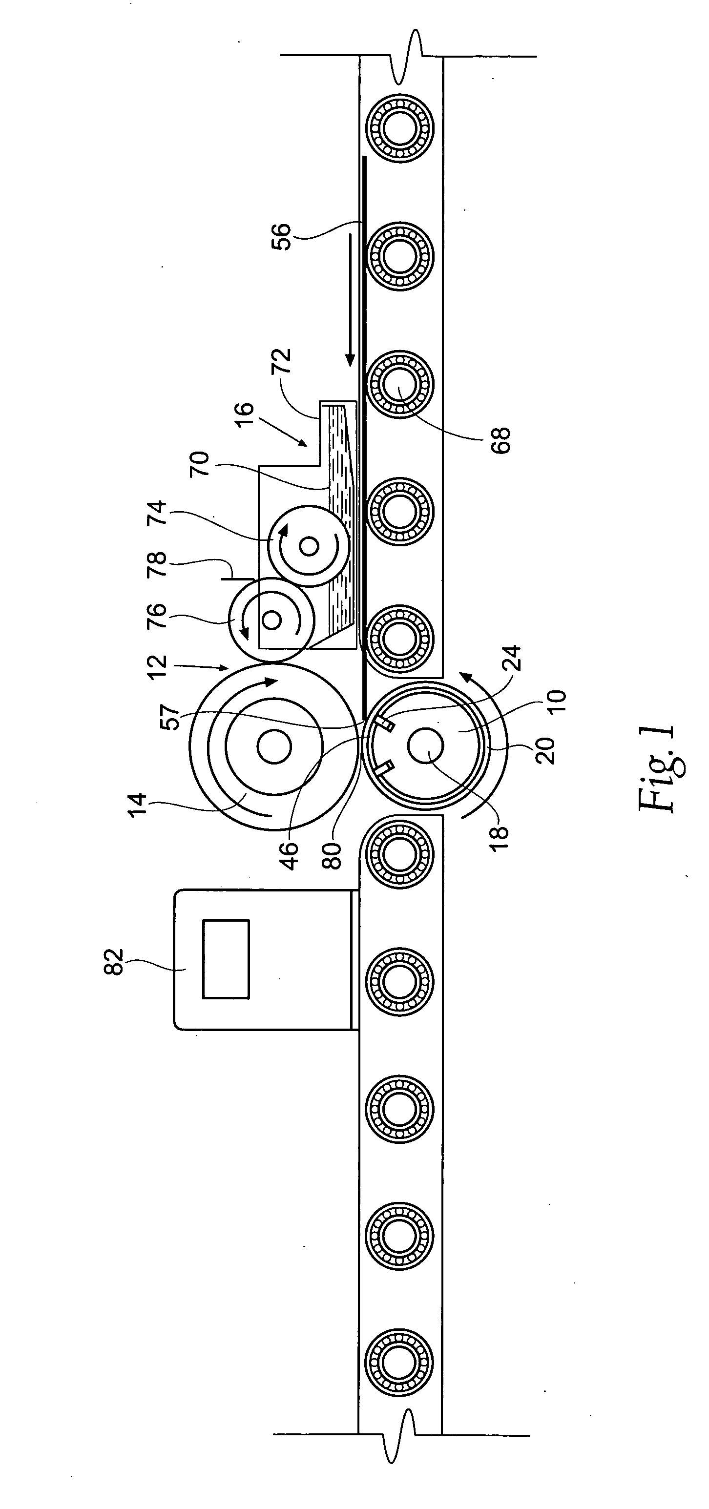
[0045] As seen in the various drawing Figures, the apparatus may be designed for use during the coating or printing of individual sheets of substrate, such as, for example, paper or cardboard, or any other suitable substrate.

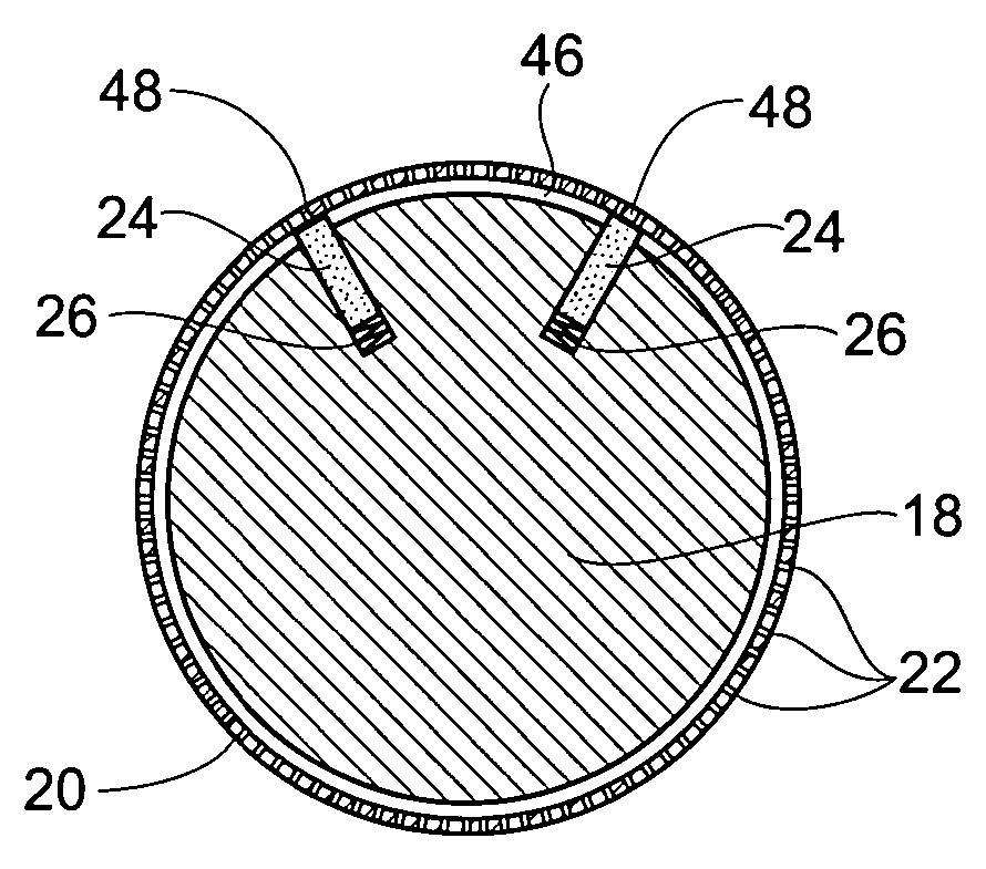
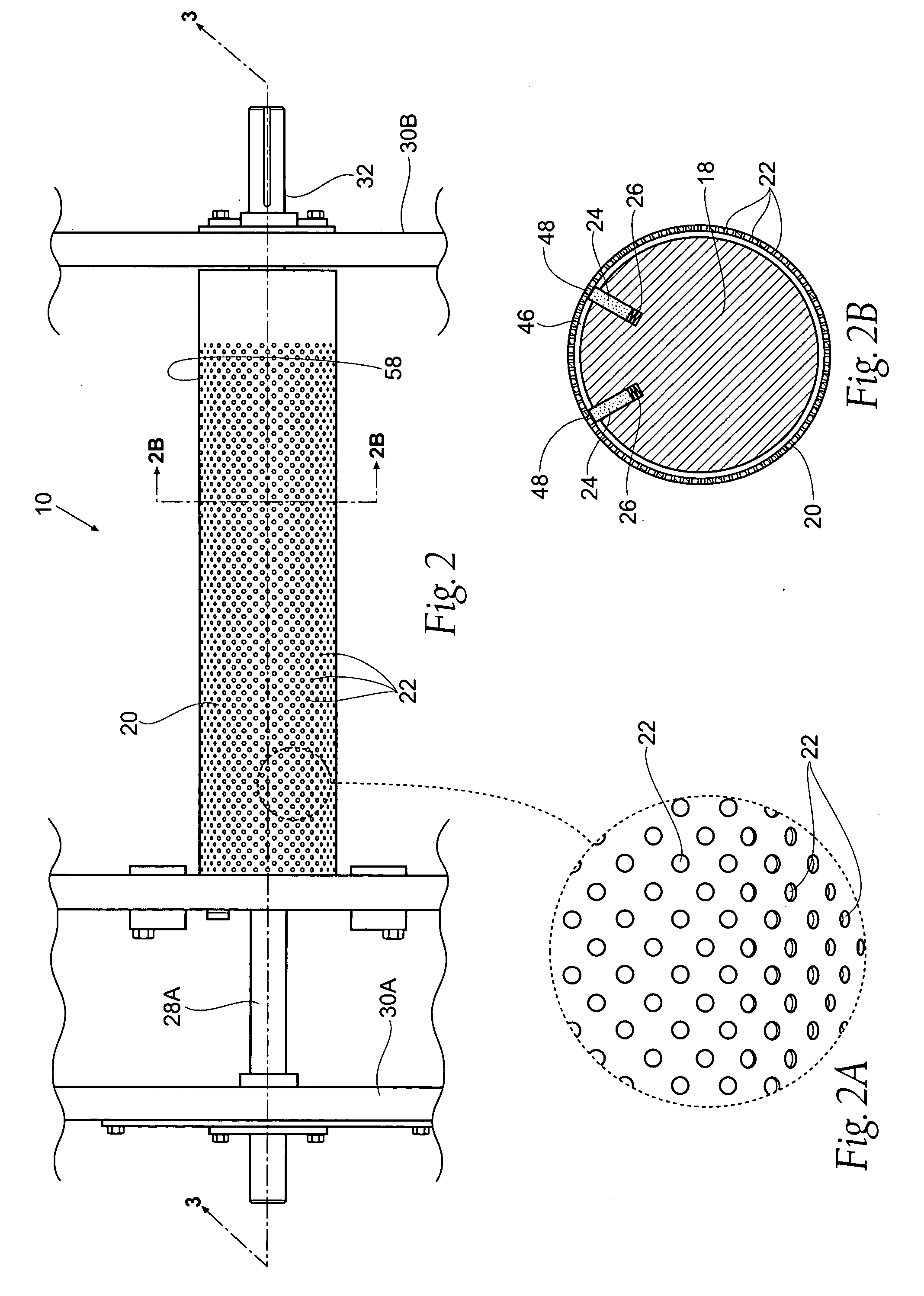
[0046] As shown in FIGS. 1-5, a preferred embodiment of the novel vacuum roller 10 is shown. As seen, the vacuum roller 10 may be use...


PUM


Abstract

An apparatus and method for retaining individual sheets of substrate in a curved configuration during coating or printing is disclosed.

Description

BACKGROUND OF THE INVENTION [0001] The present invention relates generally to an apparatus and method for retaining individual sheet substrates, especially paper or cardboard in a curved configuration during printing or while applying coating material, such as UV-curable coating. [0002] It is often desirable to coat printed substrates, such as paper or cardboard, to thereby protect the printed surface from smudging and water damage. Particularly durable coatings of this type are those cured by exposure to UV rays. Typically, the substrate surface to be coated is dropped onto a conveyor where it moves toward a coating station having a fountain system, for example. The fountain system may include a continuous coating surface, such as a coating / transfer roller for applying a coating. If UV curable coating is to be used, the coated substrate is moved away from the coating station and toward a UV source where it is exposed to UV radiation for a predetermined amount of time to thereby cur...

Claims


Application Information

Patent Timeline
IPC IPC(8): B41F27/00
CPCB41F13/18B65H2406/3614B65H2406/33B65H27/00
Inventor BEAUDRY, WALLACE J.
Owner BEAUDRY WALLACE J
Why Eureka
Try Eureka