Externally expandable heart valve anchor and method

a heart valve and anchor technology, applied in the field of endovascular replacement of heart valves, can solve the problems of heart failure, stroke, heart valve replacement surgery is a highly invasive operation with significant concomitant risk, and adverse reactions to anesthesia medications, so as to reduce paravalvular leakage or regurgitation and enhance radial strength

Inactive Publication Date: 2005-06-23
BOSTON SCI SCIMED INC
View PDF99 Cites 1222 Cited by
  • Summary
  • Abstract
  • Description
  • Claims
  • Application Information

AI Technical Summary

Benefits of technology

The present invention relates to methods and devices used to replace damaged heart valves through minimally invasive procedures. Specifically, this invention describes an improved design for an expansible anchor with which a new heart valve can be attached. This device has several advantages over previous designs including better ability to prevent leaks (paravalvular) between the new valve and old tissue, increased flexibility during deployment, and greater stability once expanded within the body. These technical improvements make it easier and safer to perform these life-changing surgeries on patients who may have previously been unable to receive them.

Problems solved by technology

The technical problem addressed in this patent text is how to improve the process of replacing damaged heart valves with minimal invasive surger y and reduce the risk of complications related to the procedure. Previous procedures involved opening the heart and removing the original valve, but this method resulted in temporary hemodynamic unstable conditions and increased the duration of the procedure. Prior art self-expanding stent based approaches also had limitations including difficulty in accurately placing the stent and potential blockages caused by fluid accumulation of the valve. Thus, there is a desire for improved tools and methods and apparatus to address these issues.

Method used


Image

  • Externally expandable heart valve anchor and method
  • Externally expandable heart valve anchor and method
  • Externally expandable heart valve anchor and method

Examples


Embodiment Construction

[0074] While preferred embodiments of the present invention have been shown and described herein, it will be obvious to those skilled in the art that such embodiments are provided by way of example only. Numerous variations, changes, and substitutions will now occur to those skilled in the art without departing from the invention. It should be understood that various alternatives to the embodiments of the invention described herein may be employed in practicing the invention. It is intended that the following claims define the scope of the invention and that methods and structures within the scope of these claims and their equivalents be covered thereby.

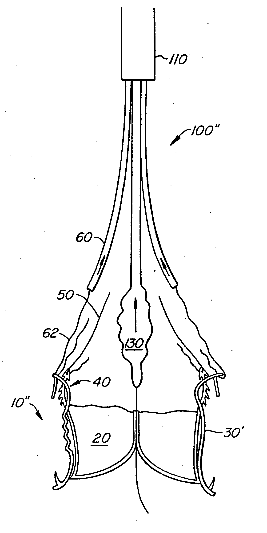
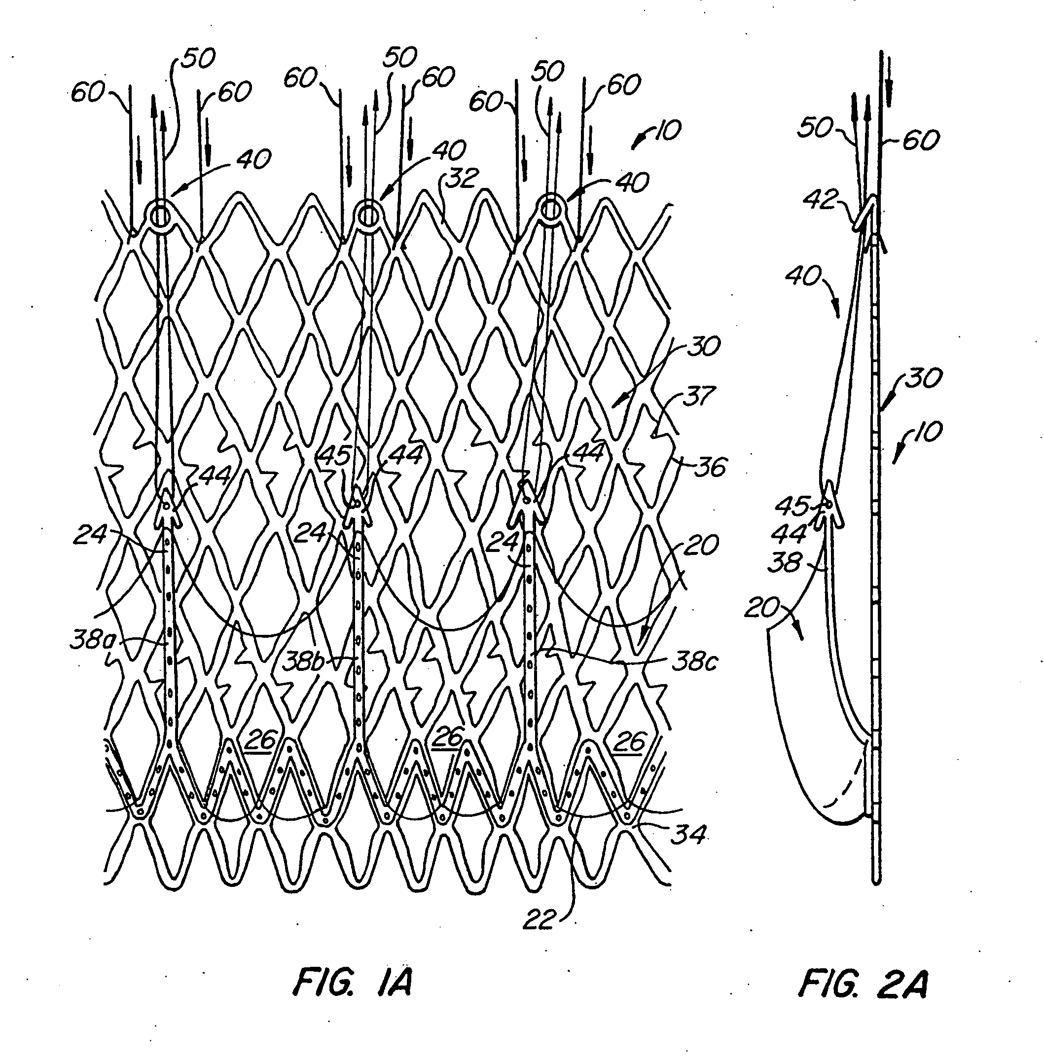
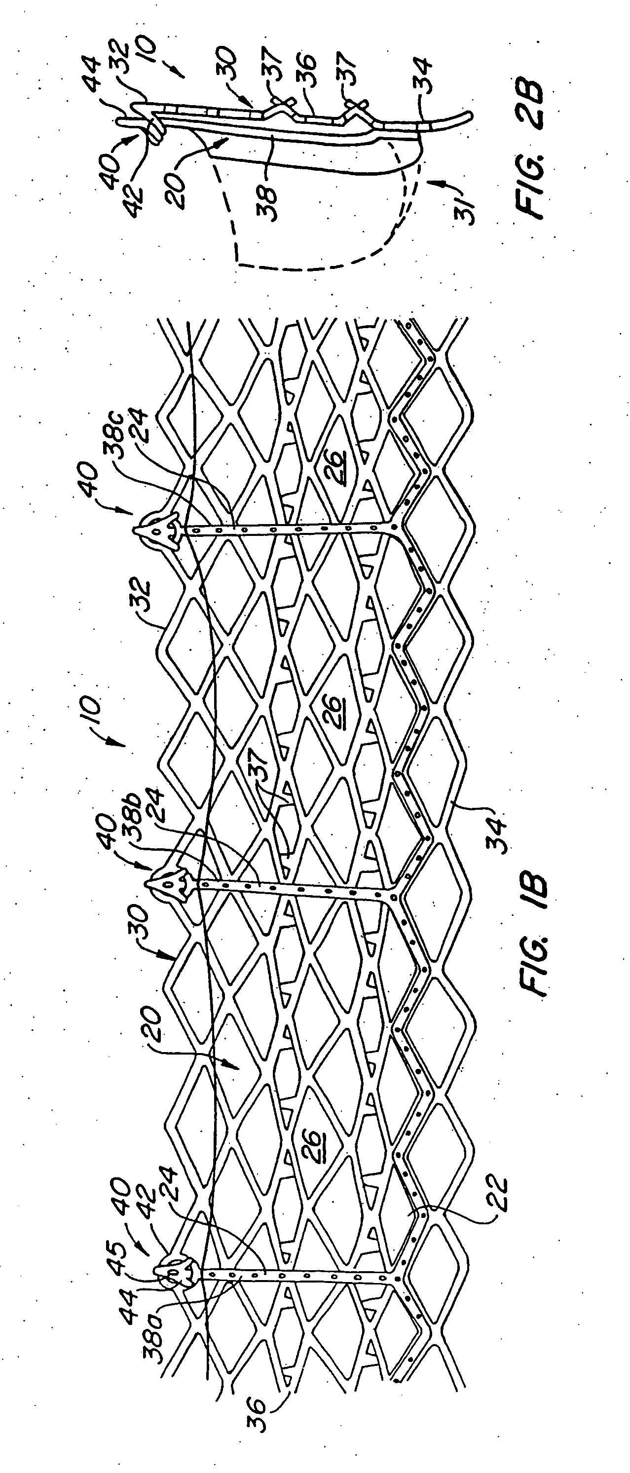
[0075] With reference now to FIGS. 1-4, a first embodiment of replacement heart valve apparatus in accordance with the present invention is described, including a method of actively foreshortening and expanding the apparatus from a delivery configuration and to a deployed configuration. Apparatus 10 comprises replacement valve 20 di...


PUM


Abstract

The invention includes methods of and apparatus for endovascularly replacing a heart valve of a patient. One aspect of the invention provides a method including the steps of endovascularly delivering a replacement valve and an expandable anchor to a vicinity of the heart valve in an unexpanded configuration; and applying an external non-hydraulic or non-pneumatic actuation force on the anchor to change the shape of the anchor, such as by applying proximally and/or distally directed force on the anchor using a releasable deployment tool to expand and contract the anchor or parts of the anchor.

Description


Claims


Application Information

Patent Timeline
Owner BOSTON SCI SCIMED INC
Why Eureka
Try Eureka