

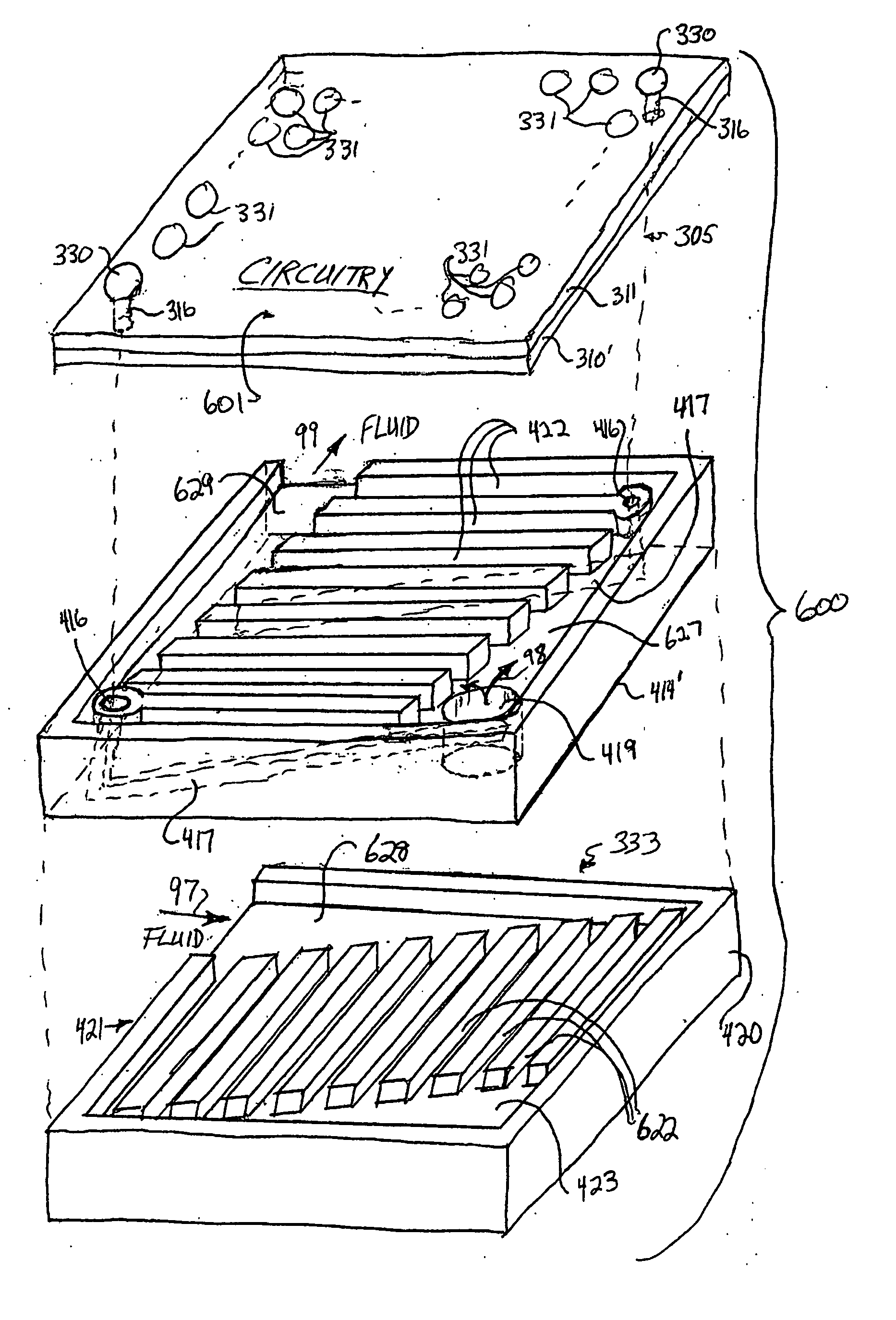
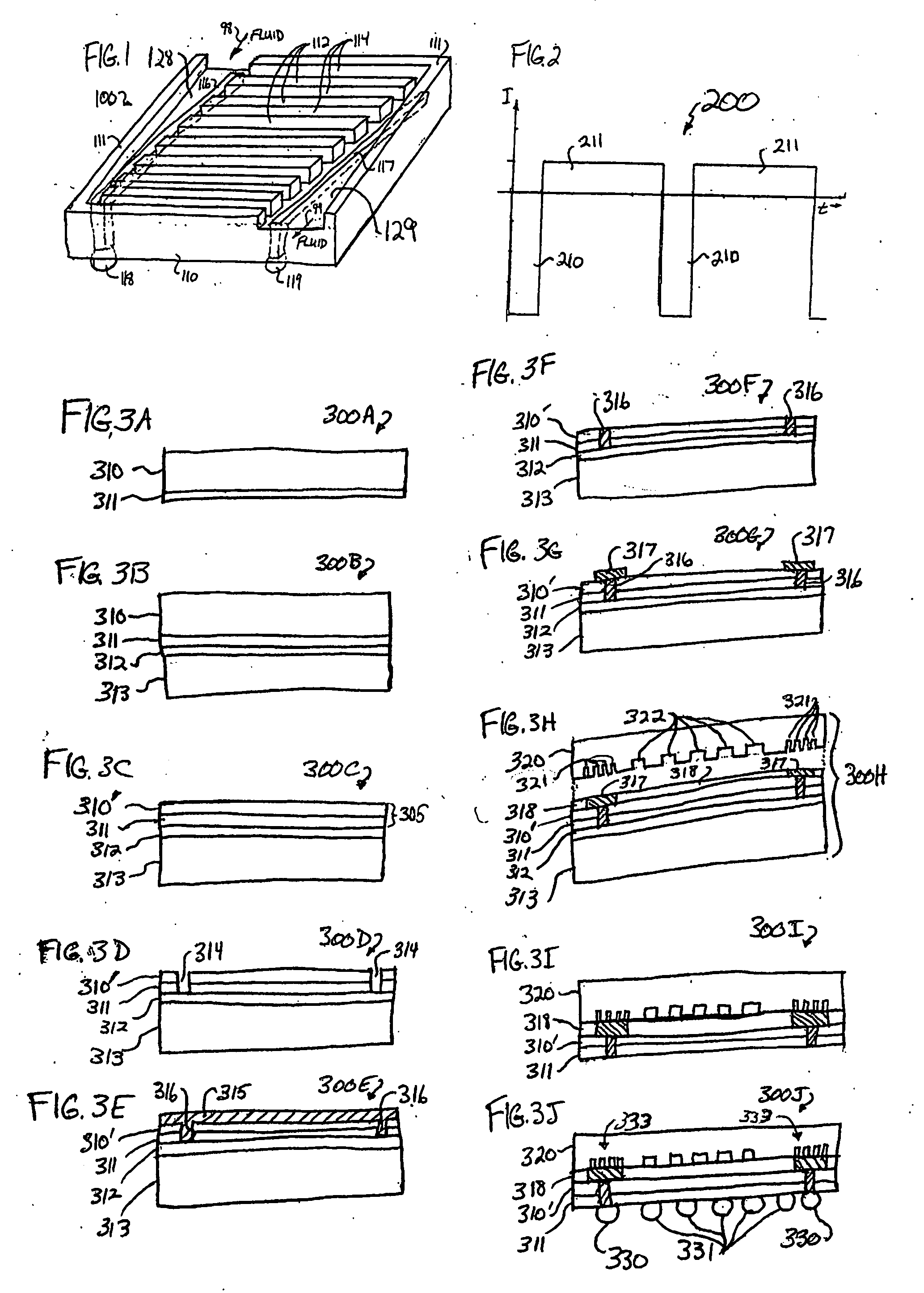
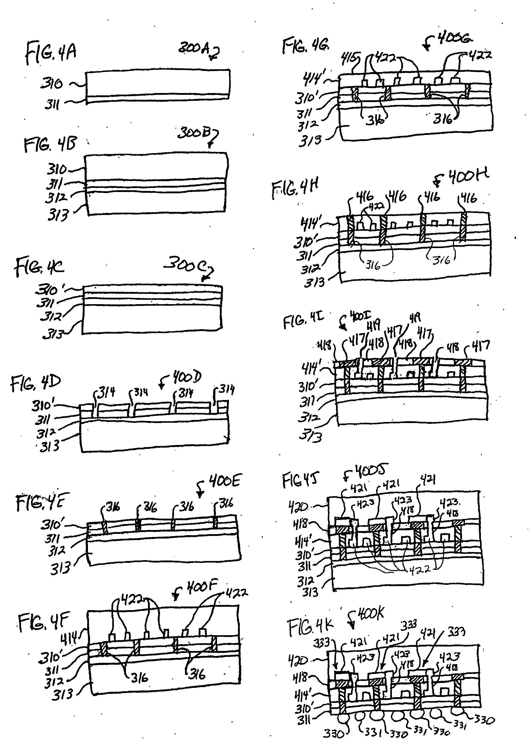
Apparatus and method integrating an electro-osmotic pump and microchannel assembly into a die package
a technology of electro-osmotic pump and microchannel assembly, which is applied in the direction of electrical apparatus, semiconductor devices, semiconductor/solid-state device details, etc., can solve the problems of considerable heat generation of circuitry on the chip, particularly a very fast chip such as a microprocessor
- Summary
- Abstract
- Description
- Claims
- Application Information
AI Technical Summary
Problems solved by technology
Method used
Image

Examples
Embodiment Construction
[0034] In the following detailed description of various embodiments, reference is made to the accompanying drawings that form a part hereof, and in which are shown by way of illustration, some specific embodiments in which the subject matter may be practiced. It is understood that other embodiments may be utilized and structural changes may be made without departing from the scope of the present invention.
[0035] The leading digit(s) of reference numbers appearing in the Figures generally corresponds to the Figure number in which that component is first introduced, such that the same reference number is used throughout to refer to an identical component which appears in multiple Figures. The same reference number or label may refer to signals and connections, and the actual meaning will be clear from its use in the context of the description.
Terminology
[0036] The terms chip, die, integrated circuit, monolithic device, semiconductor device, and microelectronic device, are used int...
PUM
 Abstract
Description
Claims
Application Information