Optical transmission apparatus

Inactive Publication Date: 2005-06-30
MITSUBISHI ELECTRIC CORP
View PDF4 Cites 0 Cited by
  • Summary
  • Abstract
  • Description
  • Claims
  • Application Information

AI Technical Summary

Benefits of technology

[0012] According to the present invention, it is possible to suppress the light surge without involving complex control and to achieve hi

Problems solved by technology

In patent document 2, there are inserted optical devices for suppressing light surge in optical transmission lines in the light surge compressing circuit and the optical output level compensating circuit, so that during normal operation their insertion losses deteriorates the qua

Method used


Image

  • Optical transmission apparatus
  • Optical transmission apparatus
  • Optical transmission apparatus

Examples


Example

Embodiment 1

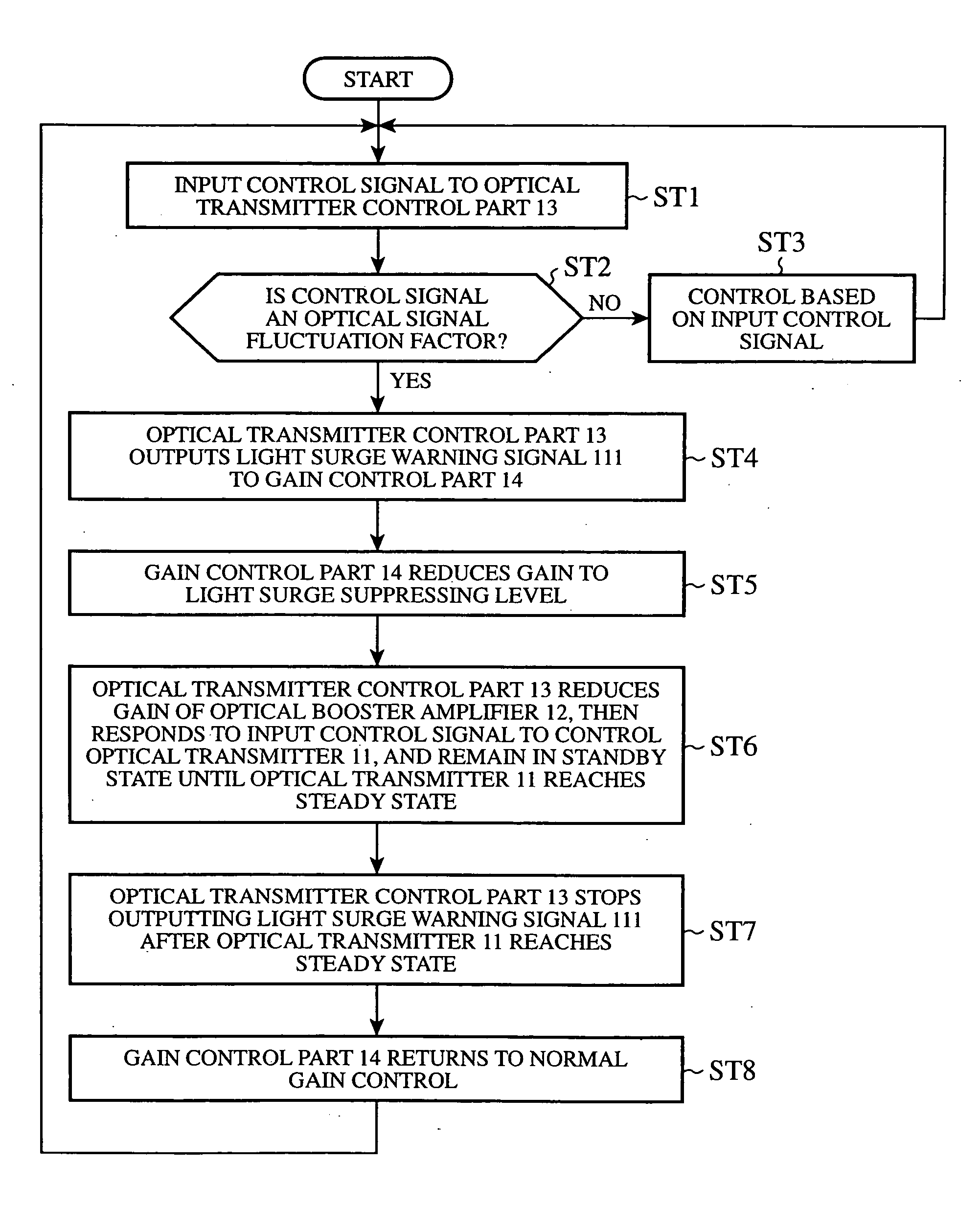
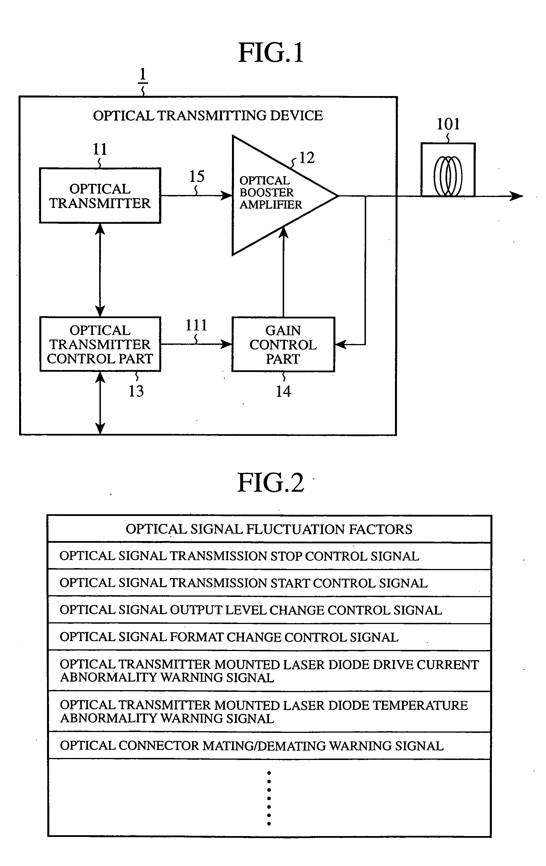
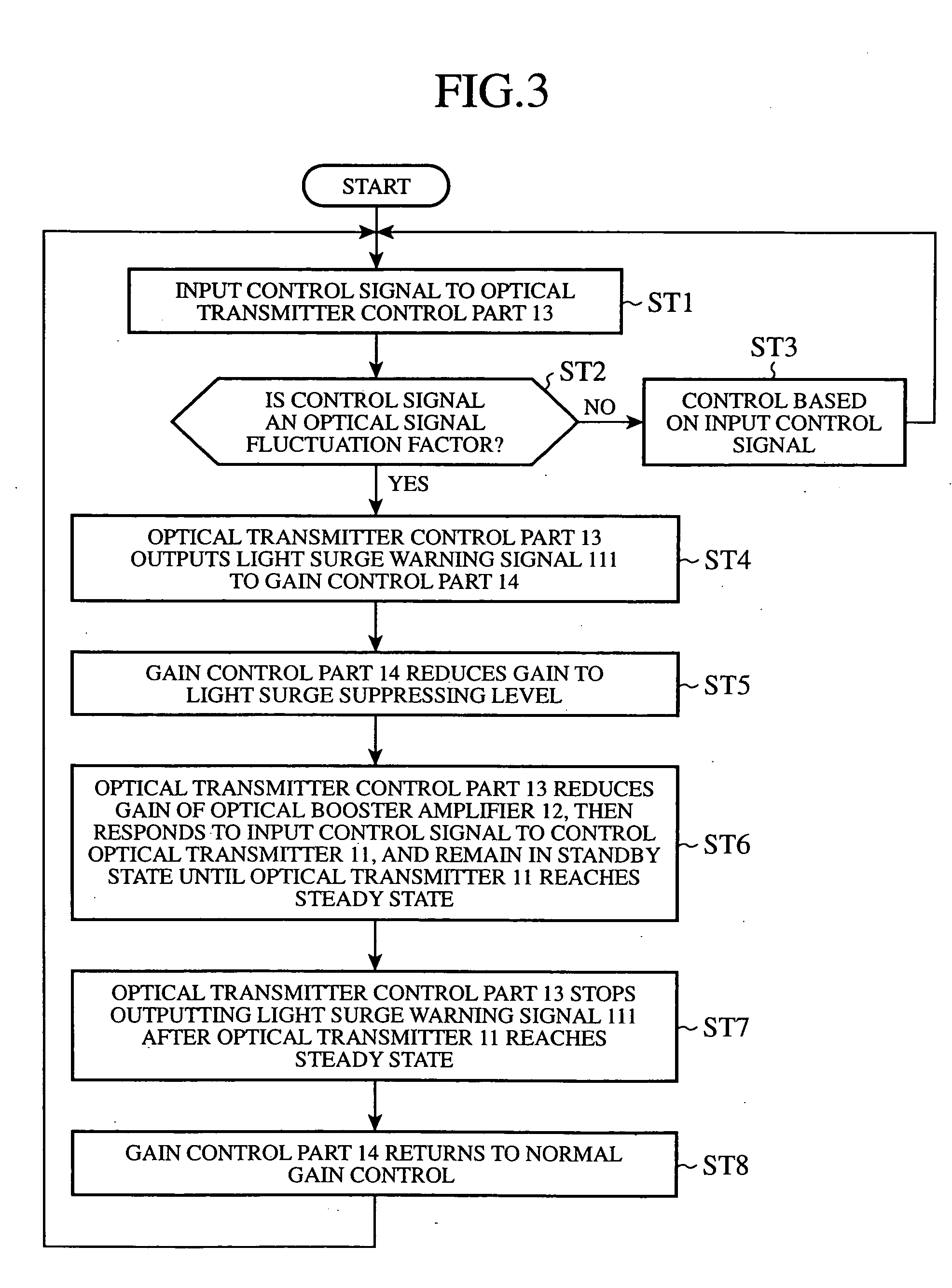
[0022]FIG. 1 illustrates in block form the configuration of an optical transmitting device in an optical transmission apparatus according to a first embodiment (Embodiment 1) of the present invention. The optical transmitting device 1 is made up of: an optical transmitter 11 for outputting an optical signal; an optical booster amplifier 12 (corresponding to the optical amplifier) for amplifying and transmitting the optical signal fed from the optical transmitter 11; an optical transmitter control part 13 (corresponding to the light surge suppressing control part) which controls the optical transmitter 11 and, upon detection of a factor which fluctuates the optical signal so greatly as to cause a light surge (corresponding to the optical signal fluctuation factor), outputs a light surge warning signal 111 prior to fluctuation of the optical signal; a gain control part 14 which controls the gain of the optical booster amplifier 12; an d an optical fiber 15 which interconn...

Example

Embodiment 2

[0046]FIG. 4 illustrates in block form an optical transmitting device and an optical receiving device in an optical transmission apparatus according to a second embodiment 2 (Embodiment 2). Those parts corresponding to the components of FIG. 1 are identified with the same reference numerals, and no description will be repeated. An optical transmitting device 1a is identical in construction with the optical transmitting device 1 of FIG. 1 except that an optical transmitter control part 13a superimposes a light surge alarm signal 112, as a monitor signal, on the optical signal from the optical transmitter 11 so as to warn an external device of the possibility of the occurrence of light surge. The optical transmitting device 1a and the optical receiving device 2 in this embodiment form part of an optical transmission system in which the suppression of light surge in the optical receiving device 2 is suppressed by use of the light surge alarm signal 112 sent from the optica...

Example

Embodiment 3

[0062]FIG. 7 illustrates in block form an optical transmitting device and an optical repeating device in an optical transmission apparatus according to a third embodiment (Embodiment 3) of the present invention. In FIG. 7 the parts identical with or corresponding to those in FIG. 4 are identified with the same reference numerals, and no description will be repeated. The optical transmitting device 1a is common in construction to the optical transmitting device 1a shown in FIG. 4. The optical transmitting device 1a and the optical repeating device 3 in this embodiment are illustrative of an optical transmission system configured to suppress the occurrence of light surge when the optical repeating device 3 is interposed between the optical transmitting device 1a and the optical receiving device 2 shown in FIG. 4.

[0063] In FIG. 7, the optical repeating device 3 comprises: an in-line optical amplifier 31 (corresponding to the optical amplifier) which receives an optical si...


PUM


Abstract

An optical transmitter 11 outputs an optical signal, and an optical booster amplifier 12 amplifies the optical signal and sends the amplified optical signal to an optical fiber 101 forming an optical transmission line. When detecting an optical signal fluctuation factor, an optical transmitter control part 13 outputs a light surge warning signal 111 prior to an optical signal fluctuation, and a gain control part 14 responds to the light surge warning signal 111 to decrease the gain of the optical booster amplifier 12 down to a level where no light surge occurs.

Description

BACKGROUND OF THE INVENTION [0001] 1. Field of the Invention [0002] The present invention relates to an optical transmission apparatus configured to suppress or inhibit the occurrence of a light surge. [0003] 2. Description of the Related Art [0004] Among conventional schemes for suppressing a light surge which gives rise to a problem in the use of an optical amplifier is an optical amplifier configuration disclosed, for example, in Document 1 mentioned below. The optical amplifier disclosed in Document 1 includes a detecting part for detecting the electric power of input light, a comparison part for comparing the value of the electric power of the input light with a predetermined value, and an output control part for controlling the gain or output of the optical amplifier. When the power of the input light is smaller than the predetermined value, the output control part reduces the gain or output of the optical amplifier, thereby keeping the peak value of a light surge small, which...

Claims


Application Information

Patent Timeline
IPC IPC(8): H04B10/032H04B10/07H04B10/077H04B10/079H04B10/293H04B10/564H04B10/572
CPCH04B10/077H04B10/2931H04B10/07955H04B10/0779
Inventor YAMANAKA, SHIGEO
Owner MITSUBISHI ELECTRIC CORP
Why Eureka
Try Eureka