Multimode optical combiner and process for producing the same

Inactive Publication Date: 2010-07-29
FUJIFILM CORP
View PDF3 Cites 4 Cited by
  • Summary
  • Abstract
  • Description
  • Claims
  • Application Information

AI Technical Summary

Benefits of technology

[0009]The first object of the present invention is to provide a multimode optical combiner which optically combines light beams by using a multimode optical waveguide without use of an optical means such as a condensing lens while providing broad options for the number of optical input ports, and outputs stable combined light having uniform cross-sectional intensity distribution while suppressing loss in the combined light.
[0016]The multimode optical combiners according to the first and second aspects of the present invention have the following advantages.
[0017](i) In the first multimode optical waveguide in the multimode optical combiner according to the first or second aspect of the present invention of the present invention, the plurality of optical waveguide portions are bundled so that none of the plurality of optical waveguide portions is located in the center of the bundle, and the multimode optical combiner (according to the first or second aspect of the present invention) is obtained by connecting the second multimode optical waveguide to the first multimode optical waveguide. Therefore, forces are uniformly exerted on the plurality of optical waveguide portions when the plurality of optical waveguide portions are bundled, so that it is possible to uniformize the characteristics of the different channels of the multimode optical combiner and the cross-sectional intensity distribution of the combined light outputted from the multimode optical combiner.
[0018](ii) Since the output end of the first multimode optical waveguide and the input end of the second multimode optical waveguide are formed so that the numerical aperture NAinput of the first multimode optical waveguide at the output end, the core diameter Dinput of the first multimode optical waveguide at the output end, the numerical aperture NAoutput of the second multimode optical waveguide at the input end, and the core diameter Doutput of the second multimode optical waveguide at the input end satisfy the aforementioned relationship (2), it is possible to suppress the loss in the combined light outputted from the multimode optical combiner (according to the first or second aspect of the present invention).
[0019](iii) Since the optical means such as a condensing lens is not used for the optical combining, and the light beams inputted into the plurality of optical waveguide portions of the multimode optical combiner (according to the first or second aspect of the present invention) are optically combined in the optical fibers realizing the first multimode optical waveguide, it is possible to stabilize the combined light outputted from the multimode optical combiner, and save the cost of the optical means. In addition, since the portion of the multimode optical combiner in which the light beams are optically combined are not exposed to the atmosphere, it is possible to simplify the cleaning operation.

Problems solved by technology

In addition, the cost of the optical means is unignorable.
Therefore, the cross-sectional intensity distribution of outputted laser light is not uniform.
Further, in the case where a lens is used for the optical combining, bothersome work for cleaning and adjustment is necessary, i.e., the time and manpower required for manufacture of the optical combiner increase.

Method used


Image

  • Multimode optical combiner and process for producing the same
  • Multimode optical combiner and process for producing the same
  • Multimode optical combiner and process for producing the same

Examples


first embodiment

[0030]Hereinbelow, a process for producing the multimode optical combiner according to the first embodiment of the present invention is explained with reference to FIGS. 1A through 5C.

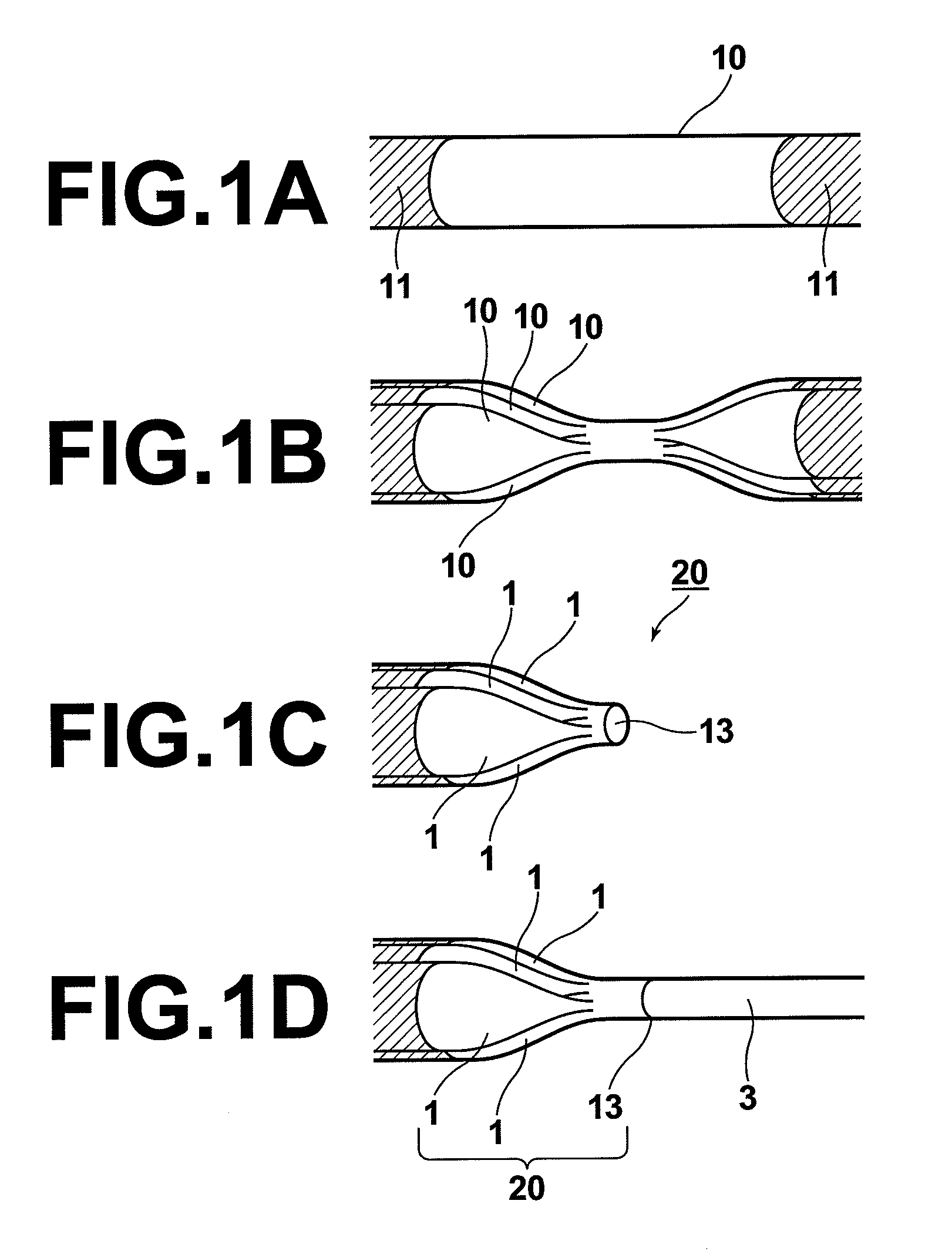
[0031]FIGS. 1A to 1D are perspective views schematically illustrating representative stages in the process for producing the input-side optical fiber according to the first embodiment.

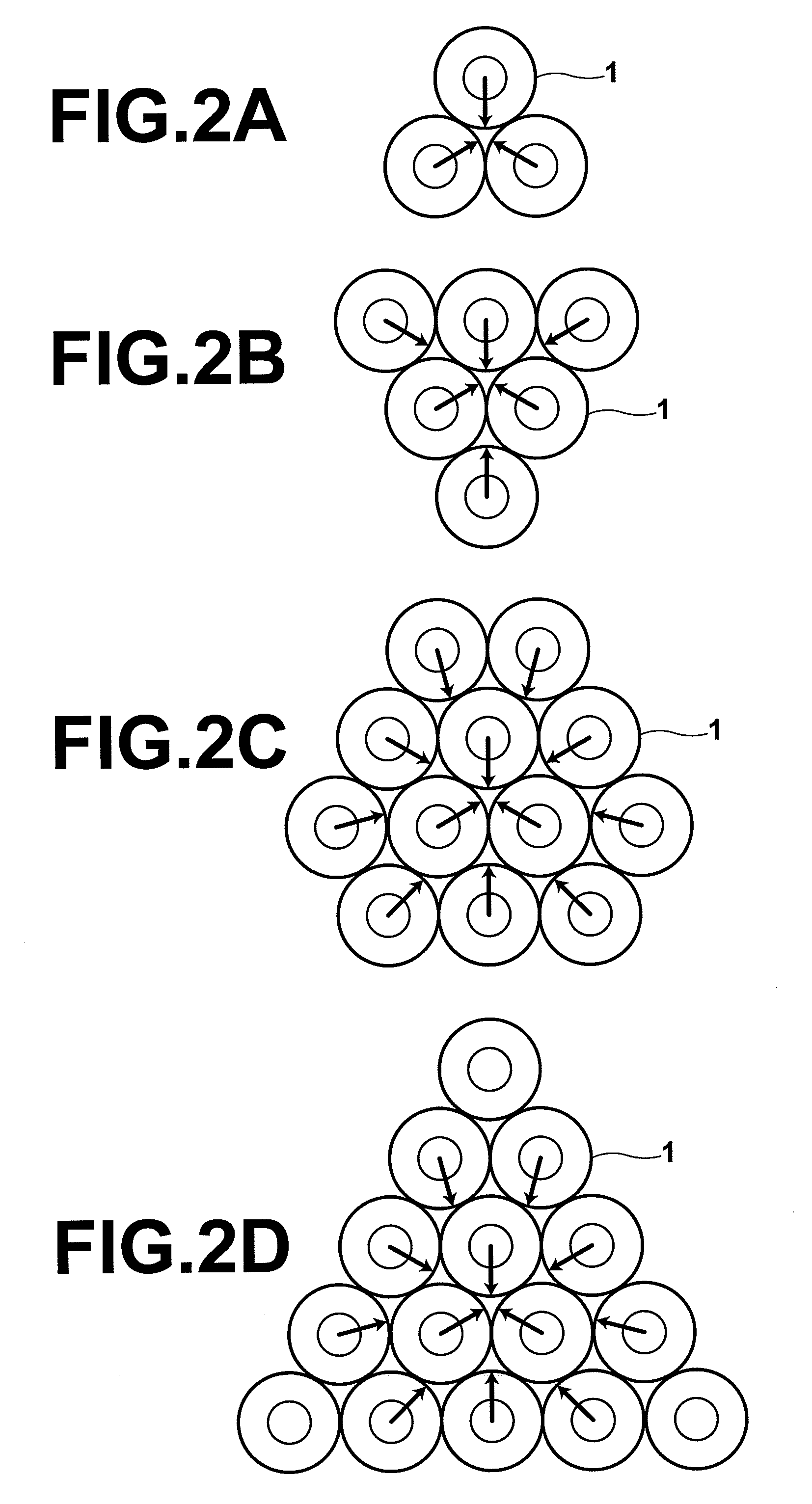
[0032]First, the coating 11 in a predetermined portion of each of a plurality of multimode optical fibers 10 is removed as illustrated in FIG. 1A. Then, the plurality of multimode optical fibers 10 are bundled in a closest arrangement so that none of the multimode optical fibers 10 is located in the center of the bundle. The number of the multimode optical fibers 10 and the manners of the closest arrangement are explained later. Subsequently, the predetermined portions of the multimode optical fibers 10 in which the coating 11 is removed are softened by heating so that the cores of the multimode optical fibers 10 in the h...

second embodiment

[0046]The multimode optical combiners according to the present invention can be produced by other processes. Hereinbelow, a process for producing a multimode optical combiner according to the second embodiment of the present invention is explained with reference to FIG. 6.

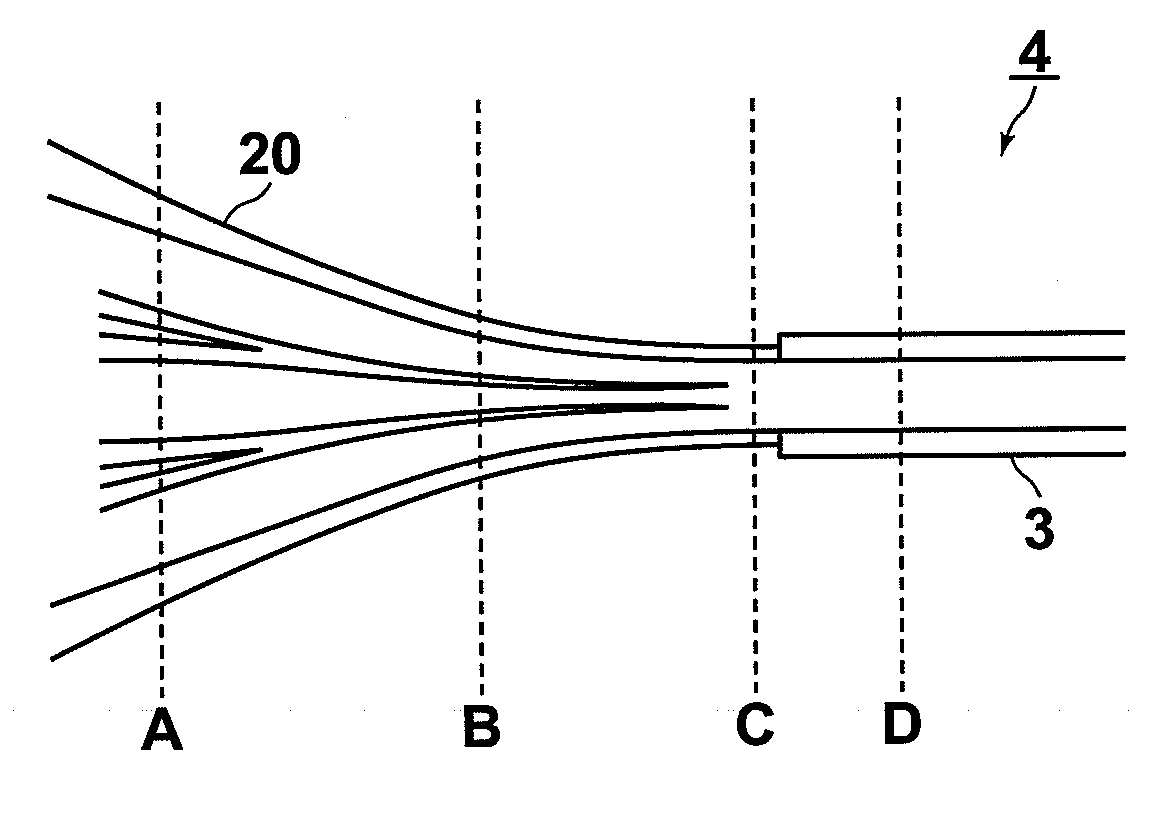
[0047]First, a plurality of multimode optical fibers are bundled, and the multimode optical fibers in a partial length of the bundle are joined into a single core, in a similar manner to the first embodiment. Then, an input-side optical fiber is produced by cutting the joined portion of the bundle of the multimode optical fibers at a position at which the core diameter is greater than the core diameter at the input end of the output-side optical fiber. The cut surface of the input-side optical fiber becomes the output end. Next, the output end of the input-side optical fiber is joined to the input end of the output-side optical fiber by fusion or the like. Then, in order to suppress the loss in the combined light, ...

third embodiment

[0049]Next, a process for producing a multimode optical combiner according to the third embodiment of the present invention is explained with reference to FIG. 7.

[0050]First, a plurality of multimode optical fibers are bundled, and the multimode optical fibers in a partial length of the bundle are joined into a single core, in a similar manner to the first embodiment. Then, an input-side optical fiber is produced by cutting the joined portion of the bundle of the multimode optical fibers at a position at which the core diameter is greater than the core diameter at the input end of the output-side optical fiber. The cut surface of the input-side optical fiber becomes the output end. Next, the core diameter of the input end of the output-side optical fiber is increased by a process of heat diffusion or the like so that the output end of the input-side optical fiber and the input end of the output-side optical fiber satisfy the aforementioned relationship (2). Thereafter, the output en...


PUM

PropertyMeasurementUnit
Diameteraaaaaaaaaa
Lengthaaaaaaaaaa

Abstract

A multimode optical combiner constituted by first and second multimode optical waveguides. The first multimode optical waveguide includes optical waveguide portions and a near-end portion having a single core and an output end. The optical waveguide portions are arranged in a bundle so that none of the at least six optical waveguide portions is located in the center of the bundle. The second multimode optical waveguide has an input end connected to the output end of the first multimode optical waveguide. The numerical aperture NAinput and the core diameter Dinput of the first multimode optical waveguide at the output end and the numerical aperture NAoutput and the core diameter Doutput of the second multimode optical waveguide at the input end satisfy the relationship, NAinput×Dinput NAoutput×Doutput.

Description

TECHNICAL FIELD[0001]The present invention relates to a multimode optical combiner which optically combines light beams emitted from light sources, by using multimode optical waveguides. The present invention also relates to a process for producing such a multimode optical combiner.BACKGROUND ART[0002]In the conventional systems in which laser beams emitted from a number of emission points are optically combined in a single multimode optical waveguide, the laser beams outputted from multimode optical fibers are coupled at a light-entrance end face of an optical fiber arranged on the output side of the multimode optical fibers, by using an optical means such as a condensing lens.[0003]In addition, the techniques for optically combining light beams by using multimode optical fibers are essential techniques for use with fiber lasers, and are currently under active development. As indicated in U.S. Pat. Nos. 5,864,644, 5,883,992, and 6,434,302, conventionally, in the case where excitati...

Claims


Application Information

Patent Timeline
IPC IPC(8): G02B6/287B23P17/00
CPCY10T29/49G02B6/287
Inventor SHIMOTSU, SHINICHI
Owner FUJIFILM CORP
Why Eureka
Try Eureka