Laser processing method

a laser processing method and laser technology, applied in the field of laser processing methods, can solve the problems of defective appearance, increased likelihood of air bubble growth and bursting, and increased likelihood of bursting, so as to achieve efficient heat in the vicinity of the first surface, and reduce the chance of bursting

Inactive Publication Date: 2009-10-01
SUMITOMO ELECTRIC IND LTD
View PDF5 Cites 12 Cited by
  • Summary
  • Abstract
  • Description
  • Claims
  • Application Information

AI Technical Summary

Benefits of technology

[0008]The present invention has been developed to eliminate the problems described above. It is an object of the present invention to provide a laser processing method that makes it possible to effectively suppress the generation of surface irregularities in a plastic member when joining the plastic member to a metal member having dissimilar chemical properties.
[0018]In the laser processing method according to the present invention, it is preferable that the intensity distributions of the respective irradiating plurality of laser beams be made uniform in accordance with a diffractive optical element. This reduces the variations in light intensity between the respective laser beams. That is, it is possible to suppress surface irregularities in the plastic member since the generation of air bubbles in the exposed surface of the plastic member caused by variations in the light intensity of the laser beams is held in check.

Problems solved by technology

Also, when the laser-induced heating progresses further in a state in which air bubbles have been formed in the vicinity of the exposed surface of the plastic member that has been locally heated by laser irradiation, the likelihood of these air bubbles growing too large and bursting increases.
The problem is that when surface irregularities are formed in the plastic member like this, it not only causes defective appearance, but insulation failure as well.

Method used


Image

  • Laser processing method
  • Laser processing method
  • Laser processing method

Examples


first embodiment

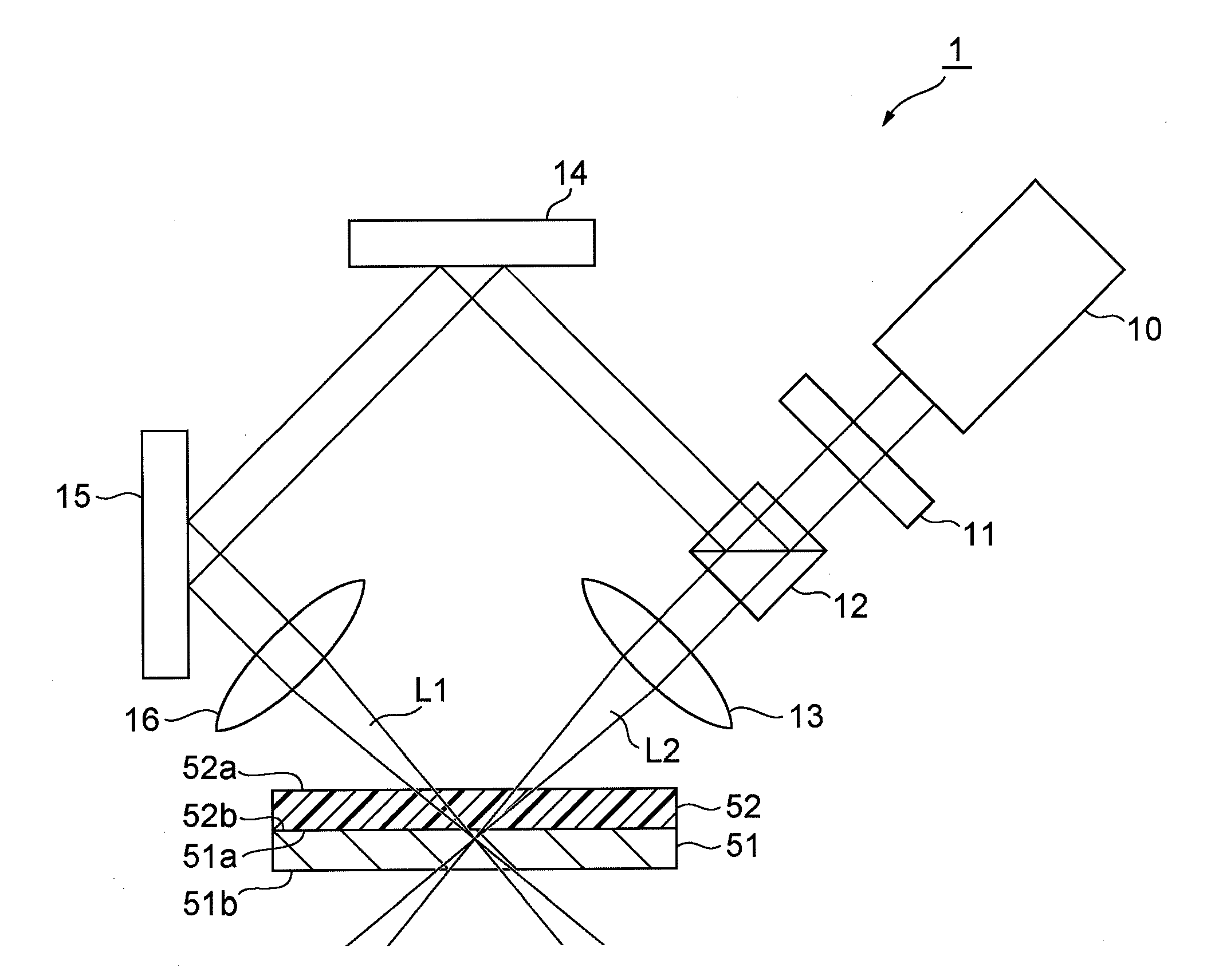
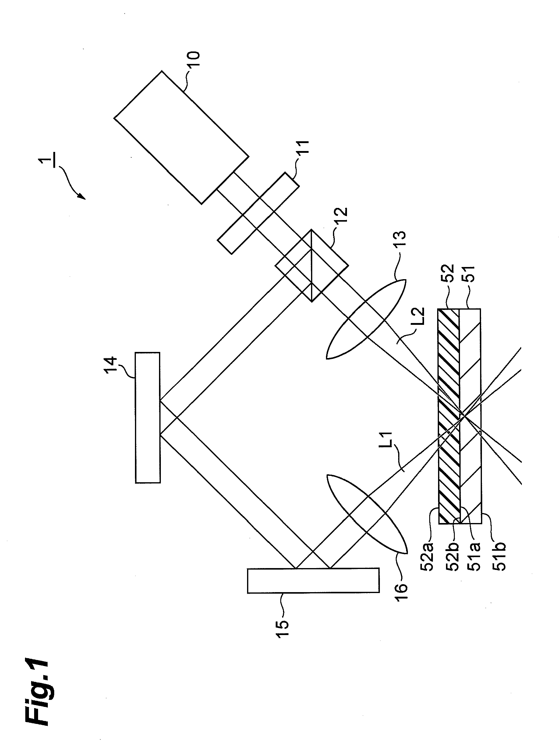
[0030]FIG. 1 is a view for explaining a first embodiment of the laser processing method according to the present invention. The laser processing apparatus 1 shown in FIG. 1 comprises a laser light source 10, diffractive optical element (DOE) 11, beam splitter 12, first lens 13, first mirror 14, second mirror 15, and second lens 16. The laser processing apparatus 1 shown in this FIG. 1 splits a laser beam from the laser light source 10 into two, and irradiates these two laser beams onto an object to be processed comprising a metal member 51 and a plastic member 52 so as to focus the laser beams in the vicinity of the surface of the metal member 51. Furthermore, the metal member 51 has a first surface 51a, and a second surface 51b that is opposite this first surface 51a, and similarly, the plastic member 52 also has a first surface 52a, and a second surface 52b that is opposite this first surface. Therefore, when the object to be processed is constituted by placing the plastic member ...

second embodiment

[0046]FIG. 4 is a view for explaining a second embodiment of the laser processing method according to the present invention. The laser processing apparatus 2 shown in FIG. 4 comprises a laser light source 10, DOE 11, first axicon lens 17, second axicon lens 18 and a lens 19. The laser processing apparatus 2 shown in FIG. 4 individually focuses a plurality of laser beams, and irradiates an object to be processed, which comprises a metal member 51 and a plastic member 52. Furthermore, in this second embodiment, the metal member 51 has a first surface 51a, and a second surface 51b that is opposite this first surface 51a, and the plastic member 52 also has a first surface 52a, and a second surface 52b that is opposite this first surface 52a. Therefore, when the object to be processed is constituted by placing the plastic member 52 on the metal member 51, the first surface 51a of the metal member 51 and the second surface 52b of the plastic member 52 make contact. Further, the interface ...

third embodiment

[0055]FIG. 6 is a view for explaining a third embodiment of the laser processing method according to the present invention. The laser processing apparatus 3 shown in FIG. 6 comprises a first laser light source 20, first DOE 21, first lens 22, second laser light source 30, second DOE 31 and second lens 32. Further, the laser processing apparatus 3 shown in FIG. 6 irradiates an object to be processed constituted from a metal member 51 and a plastic member 52 by individually focusing a plurality of laser beams. In this third embodiment as well, the metal member 51 has a first surface 51a, and a second surface 51b that is opposite this first surface 51a, and the plastic member 52 also has a first surface 52a, and a second surface 52b that is opposite this first surface 52a. Therefore, when the object to be processed is constituted by placing the plastic member 52 on the metal member 51, the first surface 51a of the metal member 51 and the second surface 52b of the plastic member 52 make...


PUM

PropertyMeasurementUnit
distanceaaaaaaaaaa
thicknessaaaaaaaaaa
thicknessaaaaaaaaaa

Abstract

The present invention relates to a laser processing method that makes it possible to effectively suppress the generation of surface irregularities on the surface of a plastic member where a metal member and a plastic member are joined together. In the laser processing method, a plurality of laser beams are irradiated from different directions so as to focus on the vicinity of an interface between the metal member and the plastic member, which are in contact with one another. The power densities of the respective laser beams at this time are set to a level not more than a level, at which the exposed surface of the plastic member on the side opposite to the interface between the metal member and the plastic member, does not melt. As a result of this, air bubbles or the like are not generated in the vicinity of the exposed surface of the plastic member, and the generation of surface roughness on the exposed surface of the plastic member is effectively suppressed.

Description

BACKGROUND OF THE INVENTION[0001]1. Field of the Invention[0002]The present invention relates to a laser processing method of using laser irradiation to join together a metal member and a plastic member, which are dissimilar materials.[0003]2. Related Background Art[0004]As one method of processing an object using laser irradiation, a method for joining a metal member and a plastic member by irradiating a laser beam of a predetermined wavelength is known.[0005]In “Laser-Assisted Metal and Plastic (LAMP) Joining,” Proceedings of the 4th International Congress on Laser Advanced Materials Processing, Seiji Katayama et al (three others) (Non-patent Document 1), there is disclosed a method in which a plastic member comprising polyamide (PA), polyethylene terephthalate (PET), polycarbonate (PC) or polypropylene (PP) is placed on a stainless steel member (SUS) prepared as a metal member, and thereafter, the SUS and plastic member are fusion bonded by irradiating a laser in the vicinity of ...

Claims


Application Information

Patent Timeline
Patent Type & Authority Applications(United States)
IPC IPC(8): B23K26/20B23K26/00B23K26/32
CPCB23K26/0021B23K26/324B23K26/0608B23K26/0604B23K26/0006B23K2103/05B23K2103/18B23K2103/42
Inventor NAKAMAE, KAZUOKAKUI, MOTOKITAMAOKI, SHINOBU
Owner SUMITOMO ELECTRIC IND LTD
Why Eureka
Try Eureka