Light source apparatus and liquid crystal display
a technology of liquid crystal display and light source, which is applied in the direction of discharge tube luminescnet screens, light source combinations, instruments, etc., can solve the problems of large loss due to light shielding by color filters, difficulty in achieving sufficient expansion of color gamut, and intensity decline from 350 cd/msup>2 /sup>2 to 235 cd/m, so as to achieve uniform intensity distribution and improve color reproduction. , the effect of improving th
- Summary
- Abstract
- Description
- Claims
- Application Information
AI Technical Summary
Benefits of technology
Problems solved by technology
Method used
Image
Examples
examples 1
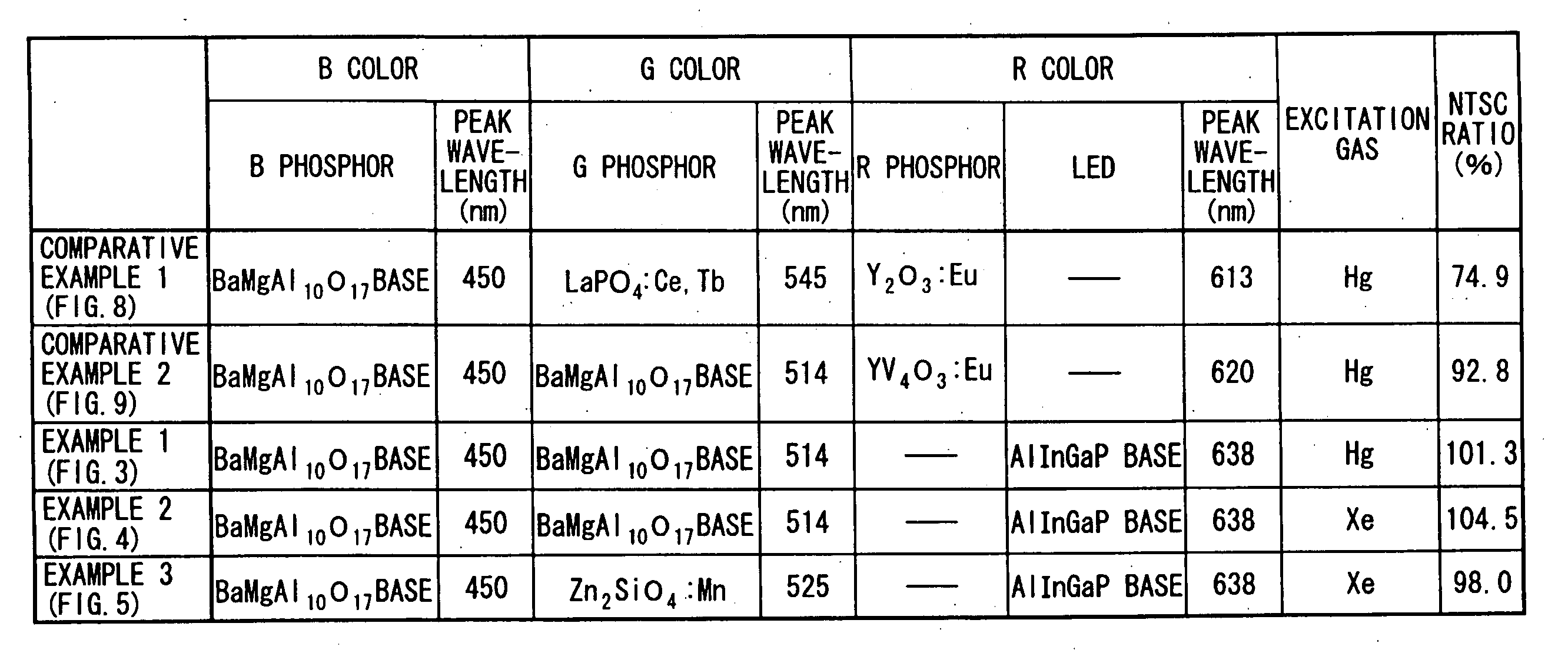
[0073]FIG. 3 shows the spectrum of the light source apparatus of Example 1 and the color filter characteristics of the LCD panel. The meanings of the horizontal axis and the vertical axis are the same as those in FIG. 8.
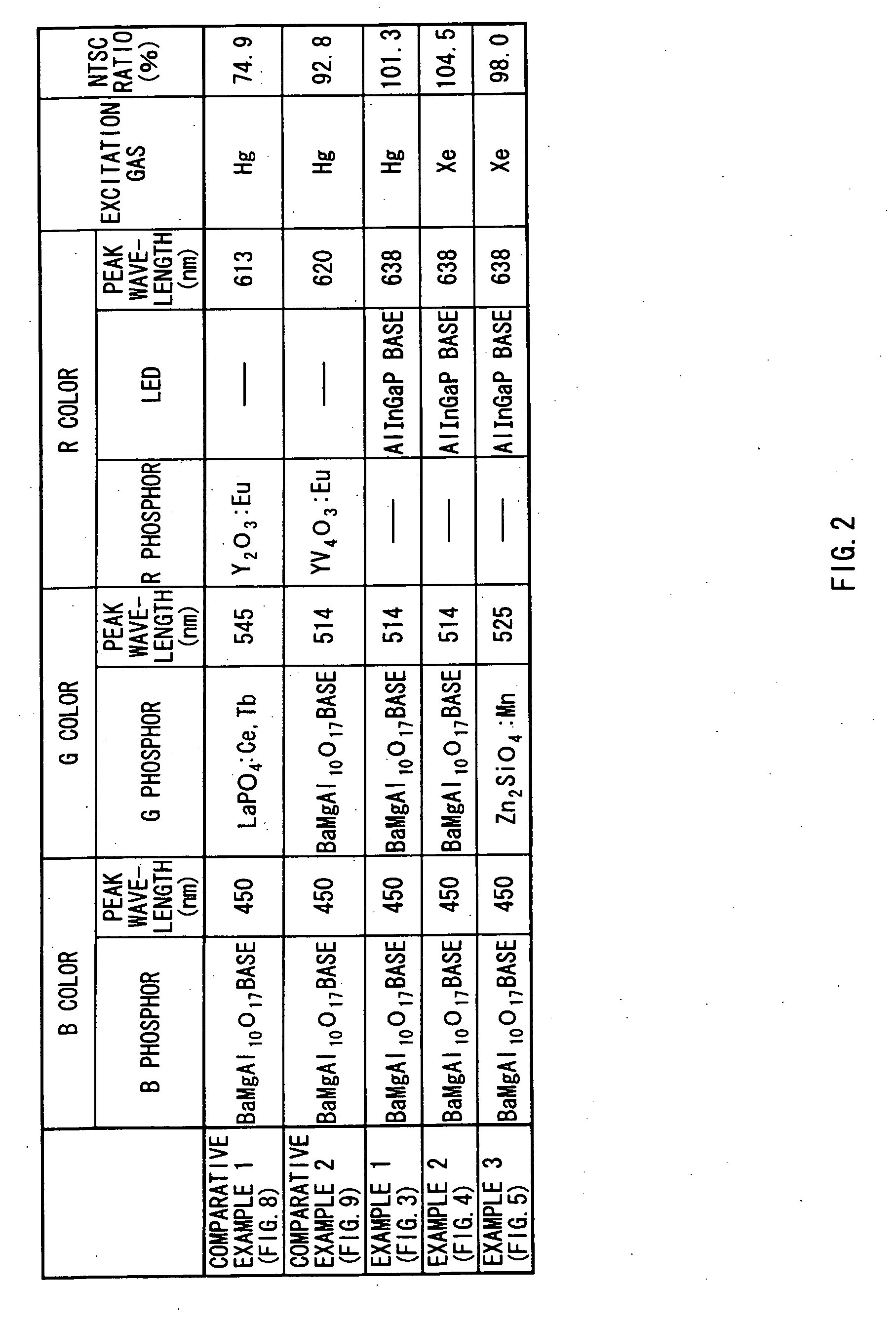
[0074] In the example, as the light source apparatus, a combination of the CCFL tube 3 to which the B phosphor and the G phosphor are applied and the LED 4 is used, and as the excitation gas, mercury is used. The B phosphor and the G phosphor of the CCFL tube 3 are the same as those in Comparative Example 2, and the LED 4 is a AlInGaP-based red light emitting diode (refer to FIG. 2). In FIG. 3, W3 indicates the emission spectrum of the combination of the CCFL tube and the LED. The meanings of CFB, CFG and CFR are the same as those in Comparative Example 1 (refer to FIG. 8).
[0075] In the emission spectrum W3, a peak PB of 450 nm is the peak of the B phosphor of the CCFL tube 3. A peak PG2 of around 510 to 520 nm (around 514 nm in FIG. 3) is a single spectrum with a ...
example 2
[0078]FIG. 4 shows the spectrum of the light source apparatus of Example 2 and the color filter characteristics of the LCD panel. The meanings of the horizontal axis and the vertical axis is the same as those in FIG. 8.
[0079] In the example, as the light source, a combination of the CCFL tube 3 to which the B phosphor and the G phosphor are applied and the LED 4 is used, and as the excitation gas, xenon (Xe) which is a noble gas is used (refer to FIG. 2). Other structures are the same as those in Example 1. In FIG. 4, W4 indicates the emission spectrum of the combination of the CCFL tube 3 and the LED 4. The meanings of CFB, CFG and CFR are the same as those in Comparative Example 1 (refer to FIG. 8).
[0080] In the example, as xenon which is a noble gas is used as the excitation gas instead of mercury, the emission line spectrums of around 404 nm, 436 nm, 546 nm and 578 nm which are unique to mercury disappear. The color gamut in the case where the light source is used as a backlig...
example 3
[0081]FIG. 5 shows the spectrum of the light source apparatus of Example 3 and the color filter characteristics of the LCD panel. The meanings of the horizontal axis and the vertical axis are the same as those in FIG. 8.
[0082] In the example, as in the case of Example 2, as the light source, a combination of the CCFL tube 3 to which the B phosphor and the G phosphor are applied and the LED 4 is used, and as the excitation gas, xenon, which is a noble gas is used (refer to FIG. 2). However, unlike Example 2, as the G phosphor, a G phosphor Zn2SiO4:Mn (P1G of Kasei Optonix, Ltd.) used in a PDP (plasma display panel) is used. As shown in FIG. 7, the emission spectrum from the G phosphor has a single spectrum with a peak wavelength of 520 to 530 nm and a half width of 45 nm or less. Other structures are the same as those in Example 2. In addition, in FIG. 5, W5 indicates the emission spectrum of the combination of the CCFL tube 3 and the LED 4. The meanings of CFB, CFG and CFR are the ...
PUM
| Property | Measurement | Unit |
|---|---|---|
| peak wavelength | aaaaa | aaaaa |
| peak wavelength | aaaaa | aaaaa |
| peak wavelength | aaaaa | aaaaa |
Abstract
Description
Claims
Application Information
 - R&D
- Intellectual Property
- Life Sciences
- Materials
- Tech Scout
- Unparalleled Data Quality
- Higher Quality Content
- 60% Fewer Hallucinations
Browse by: Latest US Patents, China's latest patents, Technical Efficacy Thesaurus, Application Domain, Technology Topic, Popular Technical Reports.
© 2025 PatSnap. All rights reserved.Legal|Privacy policy|Modern Slavery Act Transparency Statement|Sitemap|About US| Contact US: help@patsnap.com


