Photoelectric measuring device

Inactive Publication Date: 2006-04-04
X-RITE
View PDF16 Cites 9 Cited by
  • Summary
  • Abstract
  • Description
  • Claims
  • Application Information

AI Technical Summary

Benefits of technology

[0009]at least one of two polarization filters is constructed to be electronically controllable and is supplied by a control electronic with appropriate control voltages. The rotation of the polarization plane and thereby the activation or deactivation of the shine suppression can be achieved simply and quickly with electronic means by application of suitable electrical signals from the control electronic.
[0010]Thus, according to the present disclosure, a device for the photoelectric measurement of a measured object is constructed especially as densitometer or color measurement device, and includes a light source (1, 2) for exposure of the measured object (6) to measurement light, a polarization filter (8) located between the light source (1, 2) and the measured object (6), a photoelectric sensor (4), a second polarization filter (9) located between the measured object (6) and the sensor (4), a measurement lens (3) which directs the measurement light originating from a meas

Problems solved by technology

This results in different measurement results before and after drying.
Solutions with physically rotatable polarization filters are however especially disadvantageous for several reasons when the measurement devic

Method used


Image

  • Photoelectric measuring device
  • Photoelectric measuring device

Examples


Example

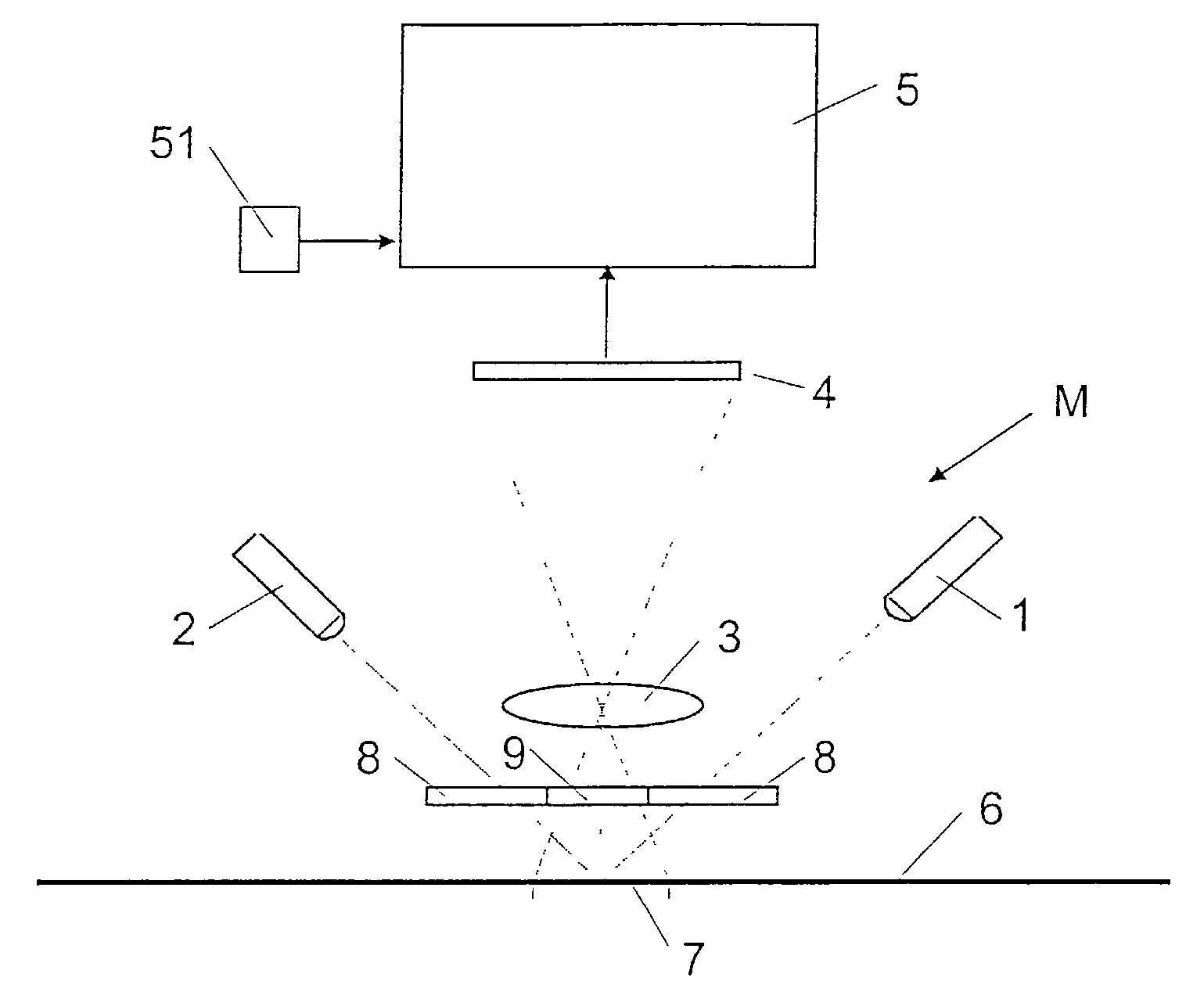
[0014]The measurement device schematically depicted in FIG. 1 (referred to in total by the reference M) is constructed as a remission measurement device and includes in a generally known manner a light source consisting of at least one lamp 1 (in this exemplary embodiment two lamps 1 and 2 are provided), a measurement lens 3, a photoelectric sensor 4 and a control electronic 5. Furthermore, a first polarization filter 8 is positioned between the lamps 1 and 2 and the object to be measured (object 6) and a second polarization filter 9 is provided between the measured object 6 and the measurement lens 3. As is common with measurement devices of this type, the lamps 1 and 2 transmit light through the first polarization filter 8 and illuminate at 45° a measurement field 7 of a measured object 6, and the measurement lens 3 captures the measurement light which is remitted from the measured object and passes through the second polarization filter 9 at 0° and directs such measurement light ...


PUM


Abstract

A device for the density or colorimetric measurement of a measured object, i.e., a densitometer or colorimeter, comprising a light source for directing measurement light onto an object to be measured, a polarization filter positioned between the light source and the object to be measured, a photoelectric sensor, a second polarization filter positioned between the object to be measured and the sensor, at least one of the polarization filters for electronic control of polarization plane orientation, a measurement lens for directing the measurement light originating from a measurement location of the measured object through the second polarization filter and onto the sensor and a controller for electronically rotating the polarization plane for one of the polarization filters relative to the other by 90°.

Description

FIELD OF THE INVENTION[0001]The invention relates to measuring devices for the photoelectric measurement and relates in particular to a densitometer or a color measuring device.BACKGROUND ART[0002]Densitometric measuring devices and systems are often equipped with polarization filters. During measurements with polarization filters, a small color density decrease results during the drying of the printing ink and an expanded range in which the color density is linearly correlated with the layer thickness of the printing ink. When the measurement result is used for the machine control during printing, the printer has a large interest to obtain measurement values as long as possible before the color is dry in order to reduce waste. A polarization device is therefor necessary.[0003]Wet printing inks have a shiny surface, while during drying the printing ink adapts to the surface structure of the paper and, depending on the paper quality, becomes more or less matte. This results in differ...

Claims


Application Information

Patent Timeline
IPC IPC(8): G01J4/00G01N21/21
CPCG01N21/21
Inventor PALLINGEN, HANS
Owner X-RITE
Why Eureka
Try Eureka