Control apparatus for vehicle

Active Publication Date: 2014-09-25
TOYOTA JIDOSHA KK
View PDF7 Cites 9 Cited by
  • Summary
  • Abstract
  • Description
  • Claims
  • Application Information

AI Technical Summary

Benefits of technology

[0010]The control apparatus according to the above aspect of the invention, the controller may be configured to set the delay time to a longer period of time as a vehicle speed is higher. With this arrangement, when the ve

Problems solved by technology

However, even if the driver wishes to keep running the vehicle only with power from the motor, the driver may temporarily depress the accelerator pedal to such an ext

Method used


Image

  • Control apparatus for vehicle
  • Control apparatus for vehicle
  • Control apparatus for vehicle

Examples


Example

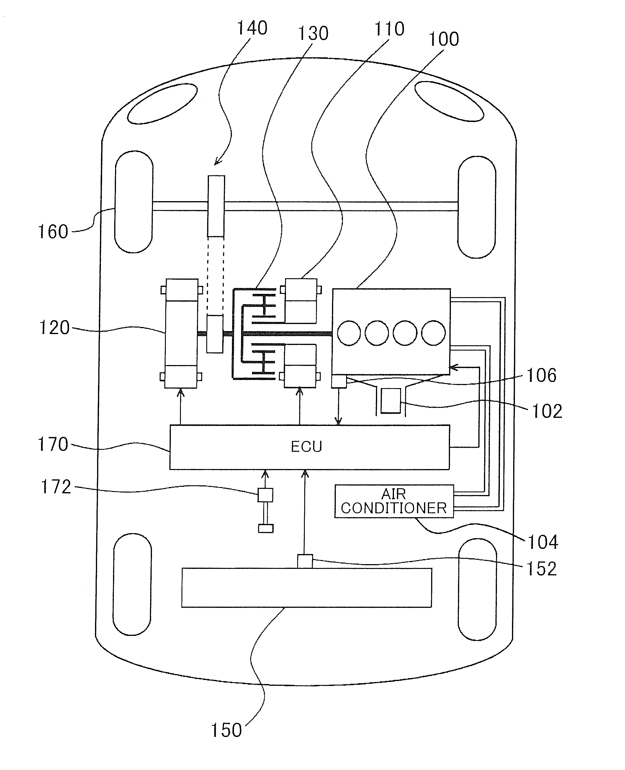
[0022]One embodiment of the invention will be described with reference to the drawings. In the following description, the same reference numerals are assigned to the same components. These components have the same names and functions. Accordingly, these components will not be repeatedly described in detail.

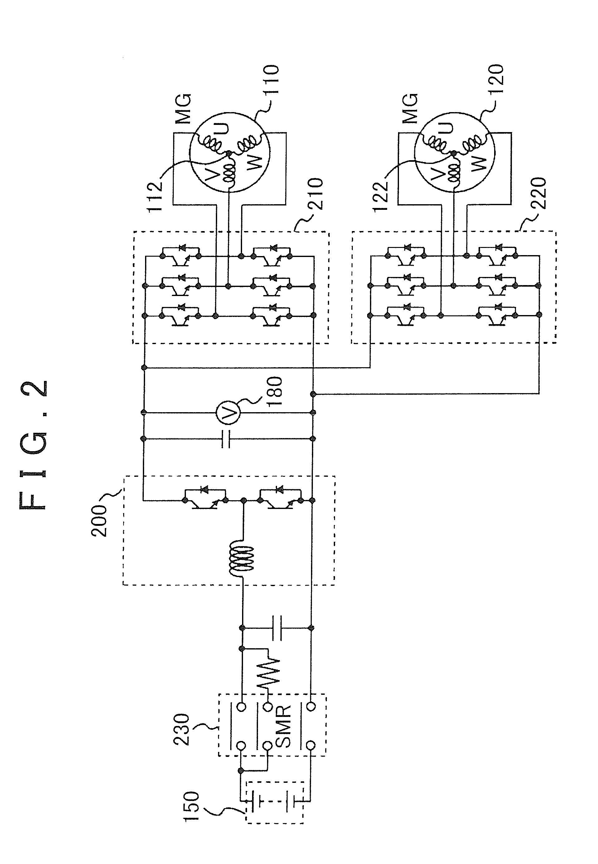
[0023]Referring to FIG. 1, an engine 100, a first motor-generator 110, a second motor-generator 120, a power split device 130, a speed reducer 140, and a battery 150 are installed on a vehicle.

[0024]The engine 100, first motor-generator 110, second motor-generator 120, and the battery 150 are controlled by an ECU (Electronic Control Unit) 170. The ECU 170 may be divided into two or more ECUs.

[0025]The vehicle shown in FIG. 1 runs with driving force delivered from at least one of the engine 100 and the second motor-generator 120. Namely, one or both of the engine 100 and the second motor-generator 120 is / are automatically selected as a drive source(s) depending on operating conditi...


PUM


Abstract

A control apparatus for a vehicle includes an engine installed on the vehicle as a drive source, an electric motor installed on the vehicle as a drive source, the electric motor being configured to run the vehicle even in a condition where the engine is stopped. The control apparatus includes a controller configured to start the engine after a given delay time elapses, if a starting condition based on an operation of a driver is satisfied, the controller being configured to keep the engine stopped if the starting condition ceases to be satisfied before the delay time elapses after the starting condition is satisfied.

Description

INCORPORATION BY REFERENCE[0001]The disclosure of Japanese Patent Application No. 2013-062196 filed on Mar. 25, 2013 including the specification, drawings and abstract is incorporated herein by reference in its entirety.BACKGROUND OF THE INVENTION[0002]1. Field of the Invention[0003]The invention relates to a control apparatus for a vehicle, and in particular to a technology for starting an engine during running of the vehicle on which the engine and an electric motor are installed as drive sources.[0004]2. Description of Related Art[0005]A vehicle on which an electric motor for running the vehicle is installed, in addition to an engine, is known in the art. The vehicle of this type is able to run using only the electric motor while keeping the engine stopped. When large driving force is required, such as when the operation amount of the accelerator pedal is increased, the engine is started so as to achieve the required driving force.[0006]As described in paragraph [0010], etc. of J...

Claims


Application Information

Patent Timeline
IPC IPC(8): B60W20/00B60W10/08B60W10/06B60L50/16
CPCB60W20/00Y10S903/93B60W10/08B60W10/06B60K6/445B60W10/26B60W20/40B60W2510/244B60W2520/10G16Z99/00Y02T10/62B60K6/22B60W10/04Y02T10/7072
Inventor ENDO, HIROKIHOKOI, KOJI
Owner TOYOTA JIDOSHA KK
Why Eureka
Try Eureka