Front cover for a module of a modular drive system

Inactive Publication Date: 2005-06-30
SIEMENS AG
View PDF6 Cites 0 Cited by
  • Summary
  • Abstract
  • Description
  • Claims
  • Application Information

AI Technical Summary

Benefits of technology

[0009] The present invention resolves prior art problems by disposing the intermediate circuit conductor rails in stepped relationship so that the intermediate circuit conductor rails can be spaced at minimal distance from each other, without regard to a configuration of the connection bracket. This saves significant space for the intermediate circuit conductor rails. The integration of a supply line in the form of two supply conductor rails which are provided with connection plugs eliminates the need for external wiring. In other words, the provision of supply conductor rails and associated connection plugs enables application of a supply voltage through all modules of a modular drive system in a simple manner. As the front-side hood is swingably and lockably connected to the front cover, the hood is captivated and prevents unauthorized persons from working on the intermediate circuit rail system of the modular drive system as unlocking or release of the hood requires a tool.
[0010] According to another feature of the present invention, a further conductor rail may be disposed on a backside of the body member of the cover at a location between the intermediate circuit conductor rails and include a contact spring arranged on one side of the conductor rail and a contact plate disposed on another opposite side of the conductor rail. As a result, a PE return line of the modular drive system through all modules is established solely by the adjoining disposition of the modules. Moreover, the provision of the PE return line renders the modular drive system less susceptible to failure, when exposed to EMC impacts.
[0011] According to another feature of the present invention, a shield may be provided for surrounding the supply conductor rails. The shield may have a rear spring tab for establishing an electric connection. The provision of the shield also protects the looped supply voltage through the modular drive system against EMC impacts.

Problems solved by technology

This saves significant space for the intermediate circuit conductor rails.

Method used


Image

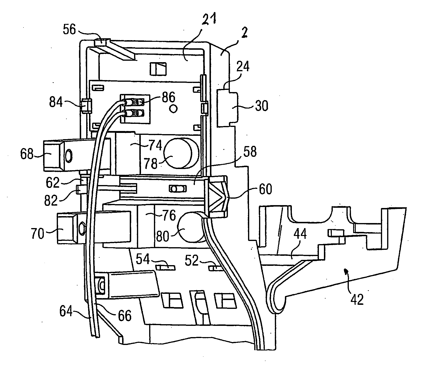
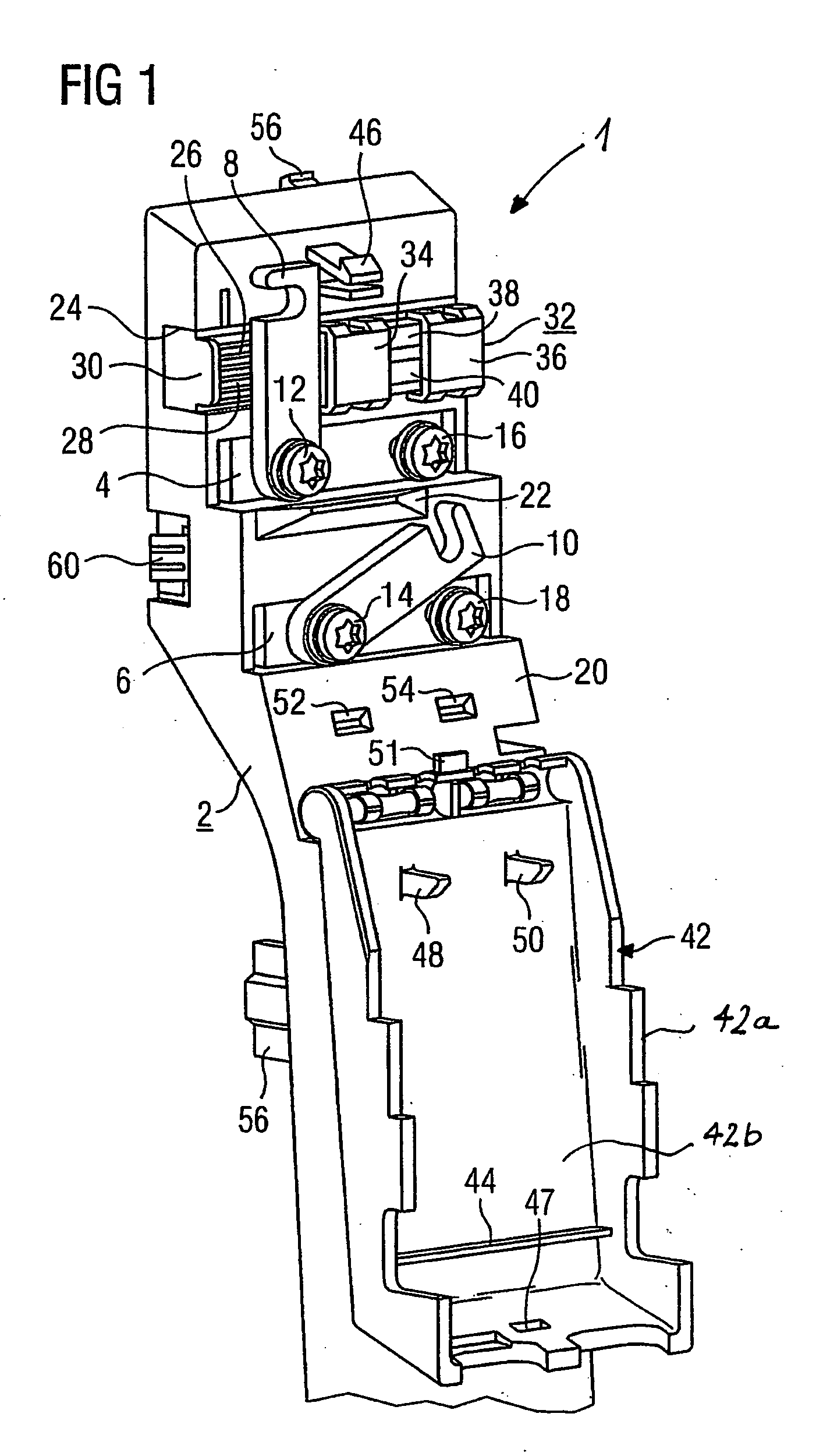
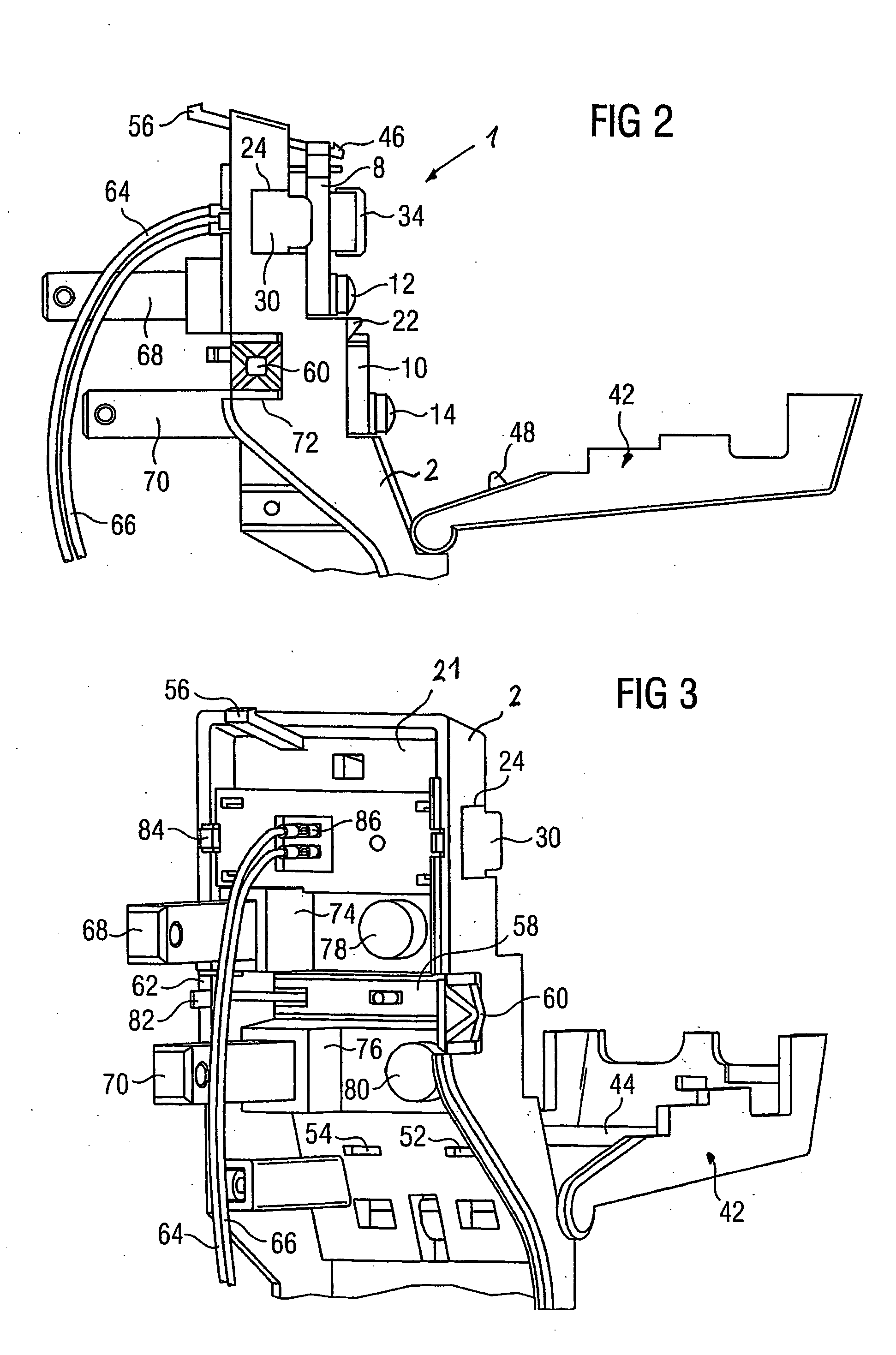
  • Front cover for a module of a modular drive system
  • Front cover for a module of a modular drive system
  • Front cover for a module of a modular drive system

Examples


Embodiment Construction

[0024] Throughout all the Figures, same or corresponding elements are generally indicated by same reference numerals. These depicted embodiments are to be understood as illustrative of the invention and not as limiting in any way. It should also be understood that the drawings are not necessarily to scale and that the embodiments are sometimes illustrated by graphic symbols, phantom lines, diagrammatic representations and fragmentary views. In certain instances, details which are not necessary for an understanding of the present invention or which render other details difficult to perceive may have been omitted.

[0025] Turning now to the drawing, and in particular to FIG. 1, there is shown a perspective illustration of an upper portion of a front cover according to the present invention, generally designated by reference numeral 1 for a module of a modular drive system. The front cover 1 has an elongate body member 2 which is provided in the upper portion on its front face 20 with t...


PUM


Abstract

A front cover for a module of a modular drive system includes two intermediate circuit conductor rails arranged in stepped relationship, two supply conductor rails, and a pivotable, engageable hood. Each intermediate circuit conductor rail includes a connection bracket, which is fixed on one end, and a contact screw. The supply conductor rails are provided with a removable connection plug, and the pivotable hood is arranged in such a way that the conductor rails can be covered and the front side of the hood is flush with the cover in the engaged state. In this way, an essentially more compact structure can be achieved, which is also less prone to interference from EMC influences, and in which a supply voltage as well as the intermediate circuit conductor rails are looped.

Description

CROSS-REFERENCES TO RELATED APPLICATIONS [0001] This application is a continuation of prior filed copending PCT International application no. PCT / DE2003 / 002080, filed Jun. 23, 2003, which designated the United States and on which priority is claimed under 35 U.S.C. §120, and which claims the priority of German Patent Application, Serial No. 102 30 393.2, filed Jul. 5, 2002, pursuant to 35 U.S.C. 119(a)-(d).BACKGROUND OF THE INVENTION [0002] The present invention relates, in general, to a module of a modular drive system having at least two modules disposed in neighboring relationship and electrically connected to each other by a d.c. voltage intermediate circuit, and more particularly to a front cover for attachment to such a module. [0003] Nothing in the following discussion of the state of the art is to be construed as an admission of prior art. [0004] Siemens-Catalog DA 65.11-2001, entitled “SIMOVERT MASTERDRIVES Motion Control”, chapter 6, in particular page 6 / 47, discloses a mo...

Claims


Application Information

Patent Timeline
IPC IPC(8): H05K7/14
CPCH05K7/1465H05K7/1482H05K7/1471
Inventor KUNICK, MATTHIASKNOBLING, THOMASLEHNER, MANFREDMASATZ, JOACHIM
Owner SIEMENS AG
Why Eureka
Try Eureka