
Vacuum processing device

Active Publication Date: 2018-12-27
ULVAC INC
View PDF0 Cites 1 Cited by
  • Summary
  • Abstract
  • Description
  • Claims
  • Application Information

AI Technical Summary

Benefits of technology

The present invention provides a vacuum processing device with a conveyance path for conveying substrates through processing regions. The conveyance path is designed in a way that it occupies less space than conventional techniques, allowing for significant space saving in the vacuum processing device. Additionally, the invention includes a substrate holder conveyance mechanism that can convey multiple substrate holders, which hold and align multiple substrates, along the conveyance path. This reduces the length of the substrate holder and its associated redundant space, resulting in even more space saving.

Problems solved by technology

The problem of this process is that sufficient space saving cannot be achieved.

Method used

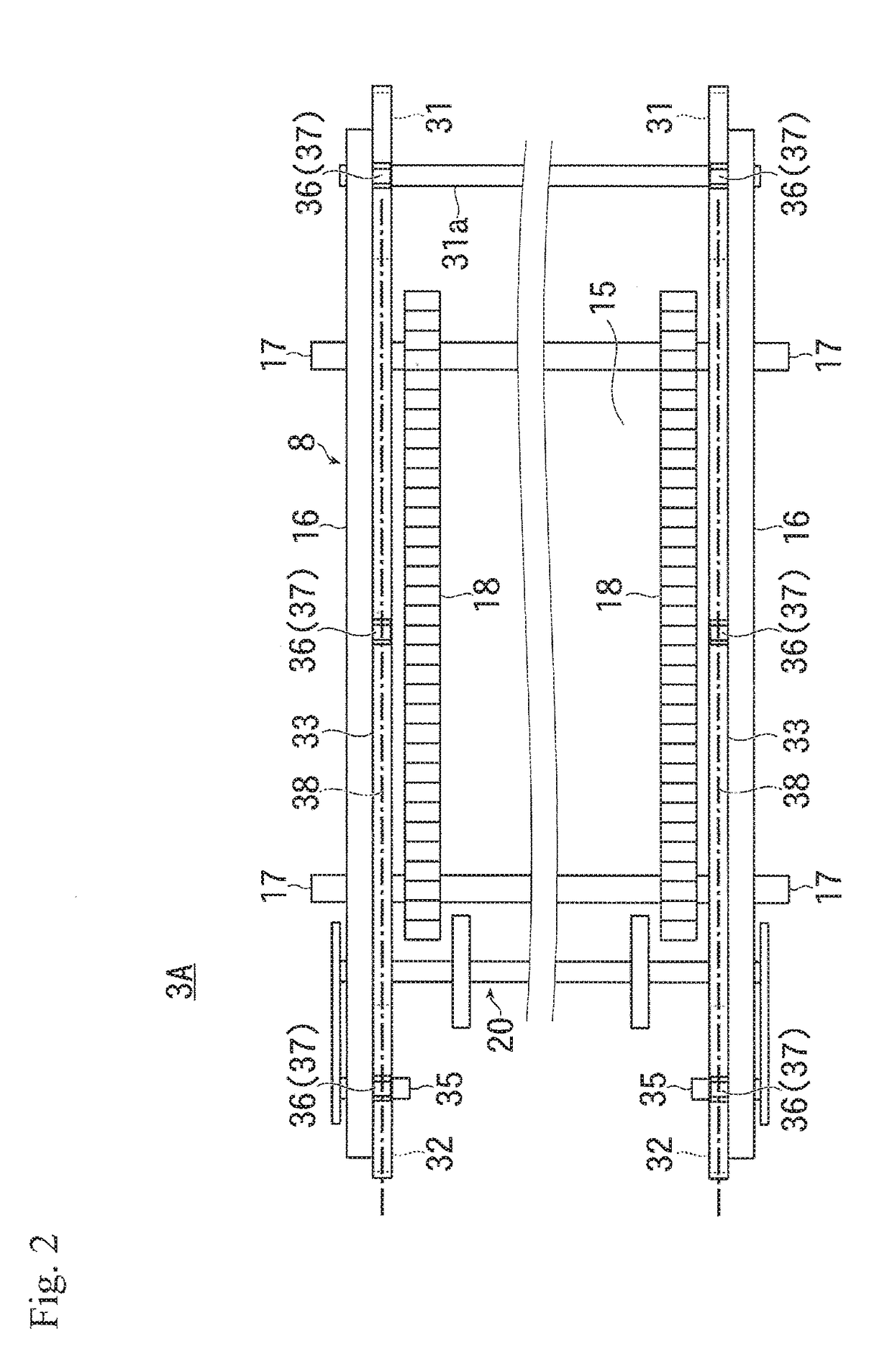
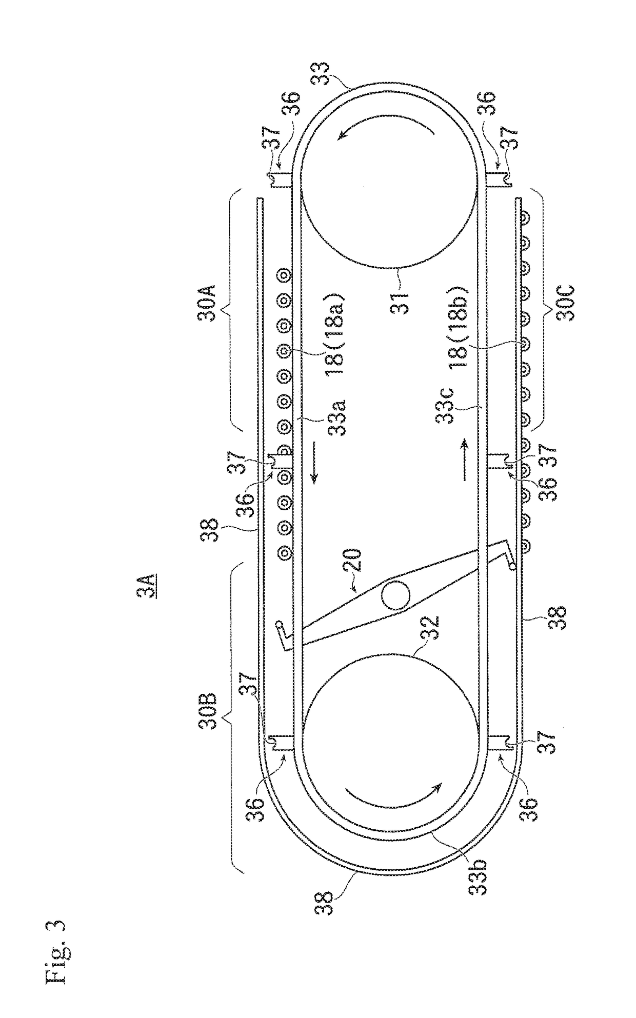

Image

  • Vacuum processing device
  • Vacuum processing device
  • Vacuum processing device

Examples


Embodiment Construction

[0056]Embodiments of the present invention will be hereinbelow described in detail with reference to the drawings.

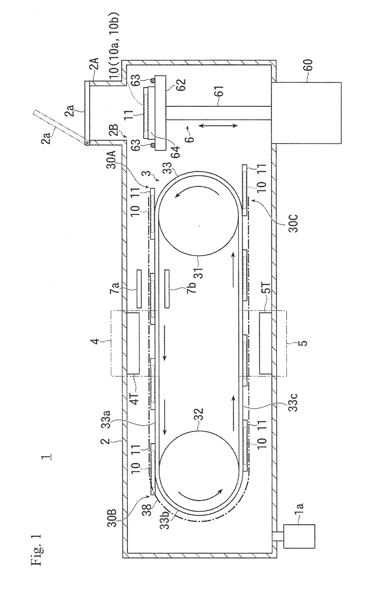
[0057]FIG. 1 is a schematic view illustrating an entire configuration of an embodiment of a vacuum processing device according to the present invention.

[0058]As illustrated in FIG. 1, a vacuum processing device 1 of this embodiment has a vacuum chamber 2 that is connected to a vacuum exhaust device 1a and where a single vacuum ambience is formed.

[0059]In the inside of the vacuum chamber 2, a substrate holder conveyance mechanism 3 that conveys a substrate holder 11 to be described later along the conveyance path is provided.

[0060]This substrate holder conveyance mechanism 3 is configured so as to continuously convey a plurality of the substrate holders 11 that hold a substrate 10 by (for example, a tray, or the like).

[0061]The substrate holder conveyance mechanism 3 used herein has first and second drive wheels 31 and 32, which are circular, and are constituted by, for e...


PUM

PropertyMeasurementUnit
Distanceaaaaaaaaaa

Abstract

The present invention provides a technique to enable sufficient space saving in a transit-type vacuum processing device. The vacuum processing device 1 of the present invention has: a vacuum chamber 2 where a single vacuum ambience is formed; first and second processing regions 4 and 5 that are provided in the vacuum chamber 2 and have a processing source that performs processing on a planar process surface of a substrate 10; and a conveyance drive member 33 that forms a conveyance path for conveying the substrate 10 so as to pass through the first and second processing regions 4 and 5. The conveyance path is formed as a single annular path when the conveyance path is projected onto a plane (vertical plane) containing: a normal line of an arbitrary point on a process surface of the substrate 10 conveyed through the conveyance path, and a trajectory line drawn by the arbitrary point on the process surface of the substrate 10 when the substrate 10 passes straight through the first and second processing regions 4 and 5.

Description

[0001]This application is a continuation of International Application No. PCT / JP2016 / 087631, filed on Dec. 16, 2016, which claims priority to Japan Patent Application No. 2015-246779, filed on Dec. 17, 2015. The contents of the prior applications are herein incorporated by reference in their entireties.TECHNICAL FIELD[0002]The present invention generally relates to a technique for a vacuum processing device that performs vacuum processing (such as, film formation) on a substrate in vacuum, and, in particular, to a technique for a through-type vacuum processing device that performs processing while a substrate holder that holds a plurality of substrates is moved.BACKGROUND ART[0003]A conventionally known vacuum processing device performs processing (such as, film formation) during passage of a plurality of substrates to be processed that are mounted on a substrate holder (such as, a tray).[0004]This type of vacuum processing device, one that has an annular conveyance path, is also kn...

Claims


Application Information

Patent Timeline
IPC IPC(8): B65G17/12B65G17/32B65G49/06H01L21/677C23C14/34
CPCB65G17/12B65G17/326B65G49/061H01L21/67706C23C14/34C23C14/50C23C14/568B65G2201/022H01L21/67109H01L21/67207H01L21/67715H01L21/6776B65G17/32H01L21/677
Inventor NAKAO, HIROTOSHI
Owner ULVAC INC
Learn More