Microchip

a microchip and microchip technology, applied in the field of microchips, can solve the problems of poor liquid separation state and sometimes impossible precise measurement of liquid, and achieve the effects of reducing the occupied space of the measuring portion, good liquid separation, and accurate measuremen

Inactive Publication Date: 2009-06-18
ROHM CO LTD
View PDF11 Cites 31 Cited by
  • Summary
  • Abstract
  • Description
  • Claims
  • Application Information

AI Technical Summary

Benefits of technology

[0008]The present invention has been made in order to solve the aforementioned problems, and an objective thereof is to provide a microchip that can measure liquid accurately and can prevent unintended flow of the measured liquid.
[0015]According to the measuring portion having a structure shown in FIG. 12, the opening for introducing the liquid and the opening for discharging the liquid are provided separately, and the width of each opening is made narrow, so that the surface area of the liquid surface of the measured liquid can be reduced. Therefore, the measurement error can be made smaller. However, there is still a problem in view of the liquid separation between the liquid within measuring portion main body 70 and the liquid flowing out in the direction of discharging flow path 80 immediately after stopping the application of a centrifugal force and in view of the occupied area of the measuring portion, so that there is still room for improvement.
[0016]Therefore, another objective of the present invention is to provide a microchip having a measuring portion by which the measurement error is small, the liquid separation between the liquid within the measuring portion main body and the liquid discharged from the measuring portion main body is good, and the occupied area within the fluid circuit can be restrained to be small.
[0028]According to the present invention, there is provided a microchip by which the liquid separation of the measured liquid is good, and the unintended flow of the measured liquid can be prevented, whereby the liquid can be measured accurately.
[0029]Also, the present invention can provide a microchip with reduced occupied space of the measuring portion. By reduction of the occupied space of the measuring portion, further scale reduction of the microchip and alleviation of the restrictions on the fluid circuit structure design can be made. Also, the present invention can provide a microchip having a measuring portion with reduced measurement error, whereby the measurement of the liquid can be made accurately. Measurement of liquid with high precision leads to improvement in the precision and the reliability of testing, analysis, and the like using a microchip.

Problems solved by technology

However, with a structure of the measuring portion that a conventional microchip such as that disclosed in Japanese Patent Laying-Open No. 2007-017342 has, there are cases in which the state of liquid separation of the liquid is poor between the measuring portion outlet and the flow path connected thereto at the time of measurement and, by this, a precise measurement of the liquid is sometimes impossible.
However, measuring portion 10 shown in FIG. 11 has the following problems and leaves room for improvement.

Method used


Image

  • Microchip
  • Microchip
  • Microchip

Examples


first embodiment

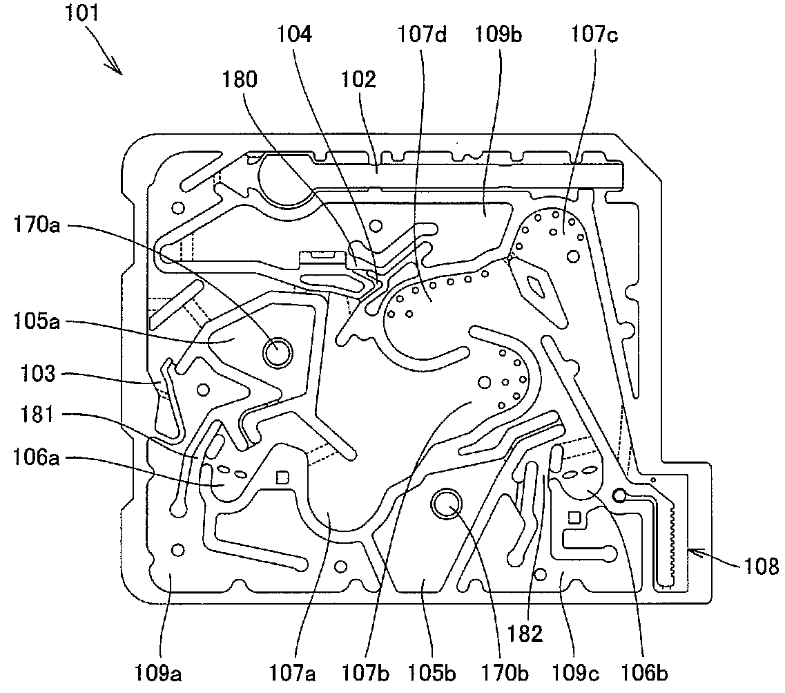
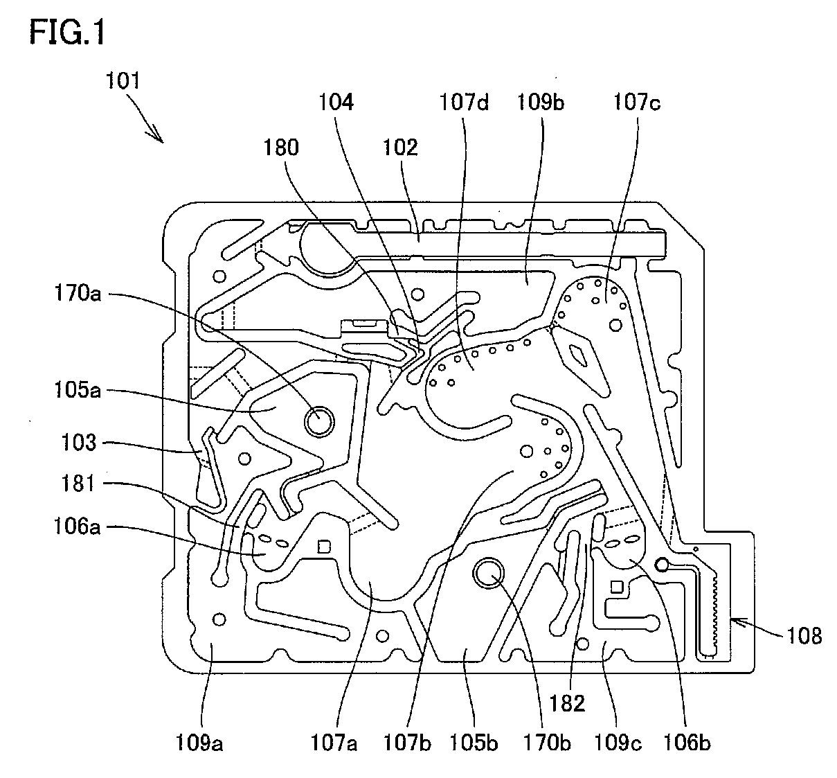
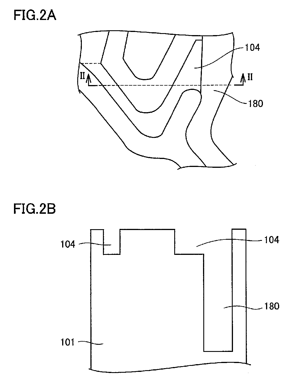
[0042]The microchip according to the present embodiment relates to a microchip having a fluid circuit therein that is formed by bonding a second substrate on a groove-forming-side surface of a first substrate having a groove formed on a substrate surface. The fluid circuit is composed of the groove formed on the surface of the first substrate and the bonding surface of the second substrate. That is, the fluid circuit is made of a hollow portion composed of the groove formed on the first substrate surface and the surface of the second substrate on the side opposite to the first substrate. The size of the microchip is not particularly limited; however, the size can have, for example, longitudinal and lateral sides of about several cm and a thickness of about several mm to 1 cm.

[0043]The shape and the pattern of the groove formed on the first substrate surface is not particularly limited, and is determined so that the structure of the hollow portion composed of the groove and the secon...

second embodiment

[0066]The microchip according to the present embodiment is a chip that can perform various chemical syntheses, testing, analysis, and others by using a fluid circuit that the chip has. In one preferable embodiment, the microchip of the present embodiment is made of a first substrate and a second substrate laminated and bonded onto the first substrate. More specifically, the microchip is formed by bonding a second substrate onto a first substrate having a groove on the surface and / or a through-hole penetrating in the thickness direction so that the groove-forming-side surface of the first substrate will oppose to the second substrate. Therefore, the microchip made of such two sheets of substrates includes a fluid circuit therein made of a hollow portion composed of the groove formed on the first substrate surface and the surface of the second substrate opposing to the first substrate. The shape and the pattern of the groove formed on the first substrate surface is not particularly li...


PUM

PropertyMeasurementUnit
widthaaaaaaaaaa
thicknessaaaaaaaaaa
thicknessaaaaaaaaaa

Abstract

A microchip is provided which includes a fluid circuit in which a first substrate having a groove provided on the surface of the substrate and a second substrate are bonded together. The fluid circuit includes at least a measuring portion for measuring the liquid and a flow path connected to one end of the measuring portion. The cross section of the measuring portion at the connecting position of the flow path and the measuring portion is shorter in length in the thickness direction of the microchip than the cross section of the flow path at the connecting position of the flow path and the measuring portion.

Description

BACKGROUND OF THE INVENTION[0001]1. Field of the Invention[0002]The present invention relates to a microchip useful as a μ-TAS (Micro Total Analysis System) or the like that is suitably used for biochemical testing of DNA, protein, cells, immunity, blood, or the like, chemical synthesis, environmental analysis, or the like, and more particularly to a microchip provided with a measuring portion for measuring liquid such as a specimen or a liquid reagent.[0003]2. Description of the Background Art[0004]In recent years, in the field of medicine, health, food, drug creation, or the like, there is an increasing importance of sensing, detecting, or quantitating a biological substance such as DNA (Deoxyribo Nucleic Acid), an enzyme, an antigen, an antibody, protein, virus, or cells as well as a chemical substance. Therefore, various biochips and microchemical chips (hereafter, these will be generally referred to as microchips) are proposed that can conveniently measure such substances. A mi...

Claims


Application Information

Patent Timeline
Patent Type & Authority Applications(United States)
IPC IPC(8): G01N1/28B01L3/00
CPCB01L3/5027B01L3/502723B01L2200/0605B01L2400/0409B01L2300/0816B01L2300/0861B01L2200/0684
Inventor MICHIUE, YOKOAOKI, YOUICHI
Owner ROHM CO LTD
Why Eureka
Try Eureka