High power single-pole electrical connector

a single-pole, high-power technology, applied in the direction of one-pole connection, connection insulation, coupling device connection, etc., can solve the problems of increasing equipment and power demands, and single-piece equipment cannot be more than eight to nine feet wide or tall, so as to reduce the overall size of any high-power electrical connector, and save spa

Active Publication Date: 2015-02-05
HUBBELL INC
View PDF16 Cites 4 Cited by
  • Summary
  • Abstract
  • Description
  • Claims
  • Application Information

AI Technical Summary

Benefits of technology

The present invention is a new type of electrical connector that allows for a larger number of smaller receptacles on a distribution panel. This is possible because the design eliminates the need for retaining rings or sealing O-rings, making it possible to use a smaller size of insulation between the contacts. Additionally, the connector is designed to be more efficient, with a smaller size and lighter weight, making it easier to handle, ship, and store. The new design also allows for the use of even larger cables, such as size 777 mcm cable. The technical effects of this new connector are improved space utilization, reduced weight, and improved handling, all while maintaining safety standards.

Problems solved by technology

In practical terms, this frequently means that single pieces of equipment cannot be more than eight to nine feet wide or tall.
These constraints have significant impact on the design of electrical distribution systems for land-based operations.
Land-based operations have become increasingly complex, with many land-based operations now involving long horizontal drilling runs or other complex, steered drilling operations.
With the increase in complexity comes an increase in the equipment and power demands.
This solution is limited, however, because there must be room to install the receptacles and make up the connections while retaining enough surface material of the panel to ensure the panel retains sufficient strength to support all the connectors and cables running to and from the panel.
For land-based oil and gas operations, this solution is limited by the size of the standard commercial truck and the desire to prefabricate the electrical box.
Given these constraints, there is limited room for change in the size of the panel.
There is, however, a drawback to this “solution.” Smaller connectors typically have lower power ratings.
This result tends to defeat the purpose of using smaller connectors.
Going to smaller connectors might only make the situation worse, by requiring use of even more connectors.
An additional amount of space is needed if the connector is to be sealed from water intrusion.
None of these variables appears subject to alteration, and in fact, prior art connectors of this type are subject to all the limitations described above.
At present, however, the standard fittings used with cable of this size (e.g., the cable clamps) are larger than a size 20 housing, and the fittings become size limiting.

Method used


Image

  • High power single-pole electrical connector
  • High power single-pole electrical connector
  • High power single-pole electrical connector

Examples


Embodiment Construction

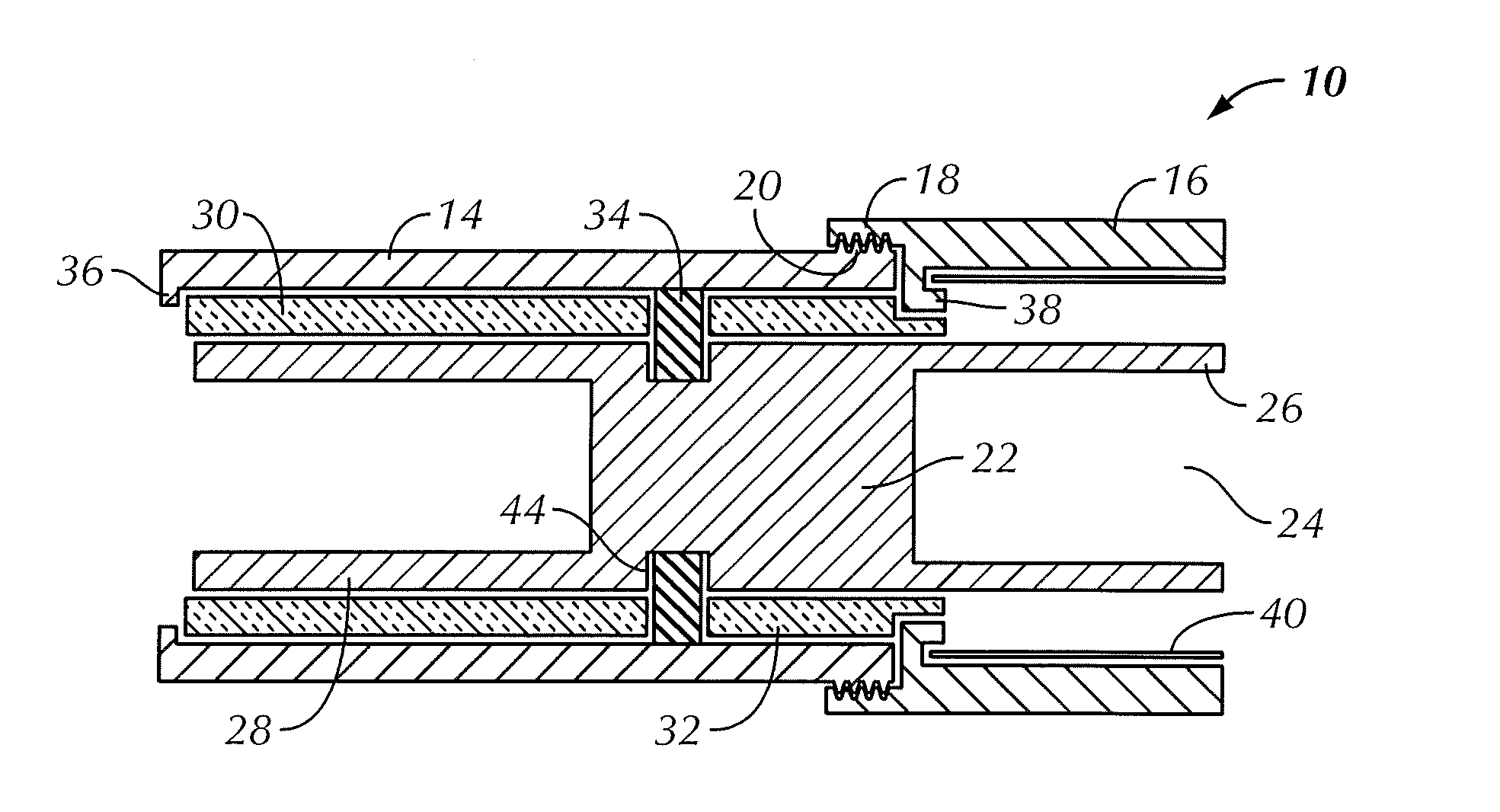
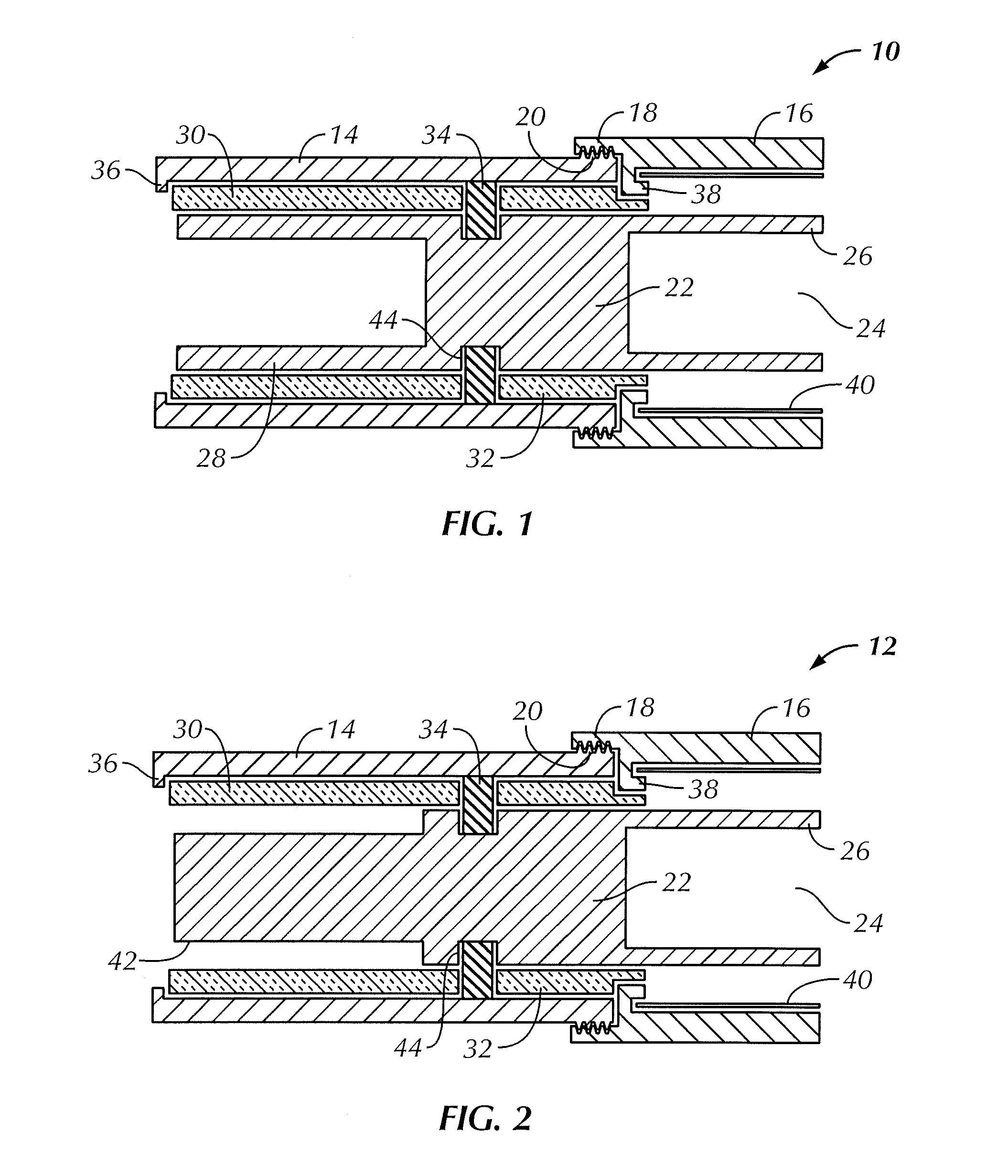
[0026]The downsized connector of the present invention is shown in cross-sectional, diagram form in FIGS. 1 and 2. A downsized female connector 10 is shown in FIG. 1, and a downsized male connector 12 is shown in FIG. 2. These are diagrammatical illustrations, showing the key components of preferred embodiments of the invention. The components of the connectors shown can be used in a panel-mounted receptacle of either male or female design. The components shown in these figures, and described in more detail below, also can be used in a cable-end plug, again of either male or female design. The installation and use of such components in these different connectors is well-known in the art.

[0027]The downsized female connector 10 shown in FIG. 1 has an outer metal shell 14 of cylindrical design. The inner surface of the shell 14 is generally smooth, and may be without any internal recesses or grooves. The shell 14 has a retaining lip 36 at one end and threads 20 at the other end. The sh...


PUM

PropertyMeasurementUnit
diameteraaaaaaaaaa
current ratingsaaaaaaaaaa

Abstract

A downsized, high-power, single-pole electrical connector is disclosed. The connector employs an insulating axial positioner between two rigid insulators, such that the insulating axial positioner maintains proper internal axial alignment while allowing for use of a smaller outer shell.

Description

FIELD OF INVENTION[0001]The present invention relates to an electrical connector, and in particular to a high power, single pole electrical connector having a reduced-size outer shell or casing.BACKGROUND AND SUMMARY OF THE INVENTION[0002]Large, high-power, single-pole electrical connectors are used in a variety of industrial settings. One such setting is the oil and gas exploration and production industry. This industry can be divided into two major segments: offshore operations and land-based operations. This distinction is important for a number of reasons, including the type of electrical systems used.[0003]Offshore oil and gas operations typically use semi-permanent electrical systems. These systems may be more resistant to the sometimes extreme environmental demands and may provide increased reliability. In these systems, there often are more hard-wired connections (i.e., as compared to land-based operations), and fewer single-pole electrical connectors of the general type dis...

Claims


Application Information

Patent Timeline
Patent Type & Authority Applications(United States)
IPC IPC(8): H01R13/502H01R43/20
CPCH01R43/20H01R13/502H01R2101/00Y10T29/49208H01R13/5025
Inventor GILLIAM, CHARLES DAVID
Owner HUBBELL INC
Why Eureka
Try Eureka